Need OEM supplier support for this product type?
Contact KOLARWIN Tools for OEM mechanic tools, private label packaging, wholesale quotation and product range support. This gives overseas buyers a clear path from article reading to supplier discussion.
Buying teams often specify a puller by bearing diameter alone, then face fit problems during sampling or field use. Internal and external pullers grip different surfaces, send force through different paths, and need different clearance. This guide gives distributors, importers, workshop suppliers, service chains, and private-label buyers a practical way to select a family, define dimensions, request QC evidence, and write a usable RFQ.
Contents
- 1. What Is the Difference Between Internal and External Bearing Pullers?
- 2. When Should Buyers Choose an External Bearing Puller?
- 3. When Does an Internal Bearing Puller Make Better Sense?
- 4. How Should Buyers Measure Bore, Spread, Reach, and Grip Depth?
- 5. How Do Counter-Stays, Slide Hammers, and Forcing Screws Differ?
- 6. Which Materials and Manufacturing Details Affect Reliability?
- 7. What Safety Controls Belong in the Product Specification?
- 8. Should Distributors Stock Separate Pullers or Combination Kits?
- 9. What Quality-Control Evidence Should Importers Request?
- 10. How Should Buyers Write the Final RFQ?
1. What Is the Difference Between Internal and External Bearing Pullers?
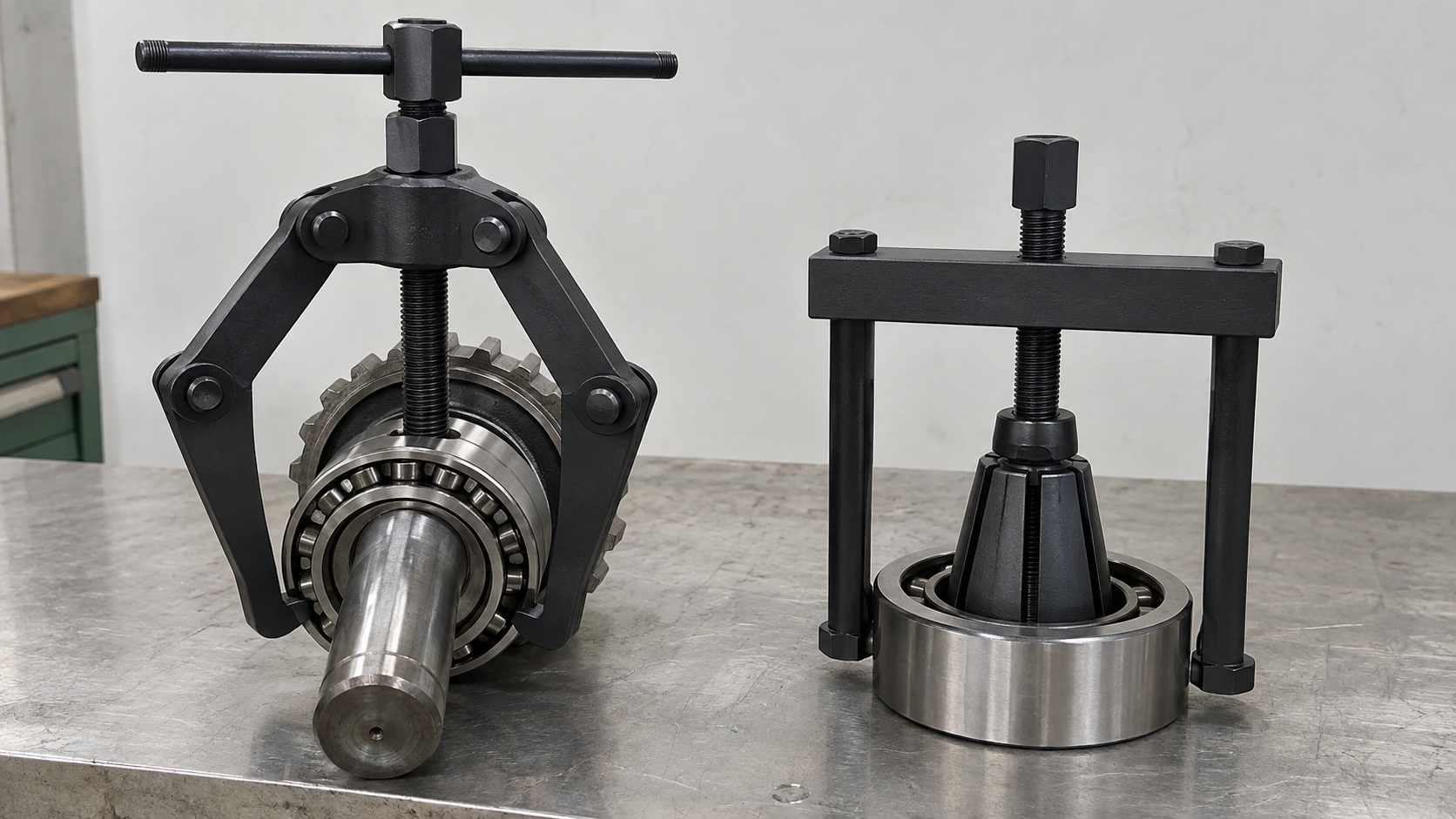
An external puller hooks behind an exposed outer edge and pulls a part away from a shaft, while an internal puller expands inside a bore and pulls an inner-held part from a housing. That grip direction matters more than a catalogue bearing number. A bearing mounted on a shaft can still have a blocked outer race, while a bearing inside a housing can leave no shoulder for outside jaws.
Start with the load path. Ask where a jaw, collet, or segment can make full contact without touching a raceway, seal, cage, or thin housing wall. For a first-pass family decision:
- Use external jaws when a sound outer shoulder remains visible around a shaft-mounted part.
- Use an internal collet or expanding jaw when a bore provides access to a blind race, cup, bush, or sleeve.
- Use a combination set only when matched components cover both access patterns.
- Treat nominal bore or outside diameter as a starting point, not proof of fit.
For distributors, a clear family split also helps staff quote correctly. A useful companion position for a catalogue could be an external and internal puller range page that groups tools by grip direction and application rather than by piece count alone.
Action recommendation: add three RFQ fields before any size field: gripping surface, part location, and available reaction point.
Mechanism comparison
| Decision point | External puller | Internal puller | Buyer check |
|---|---|---|---|
| Primary contact | Outer shoulder, hub edge, or exposed race | Inner bore, raceway land, cup, bush, or sleeve | Confirm full contact surface |
| Typical access | Open around shaft-mounted part | Bore access, often inside a blind housing | Record access direction |
| Main risk | Jaw slip or uneven loading | Segment slip or housing damage | Request engagement limits |
| Force direction | Jaws pull outward while screw or actuator reacts centrally | Collet expands, then bridge or hammer pulls axially | Check reaction path |
| Common adjustment | Jaw spread, reach, tip thickness | Bore range, grip depth, collet profile | Match working range, not maximum range |
2. When Should Buyers Choose an External Bearing Puller?
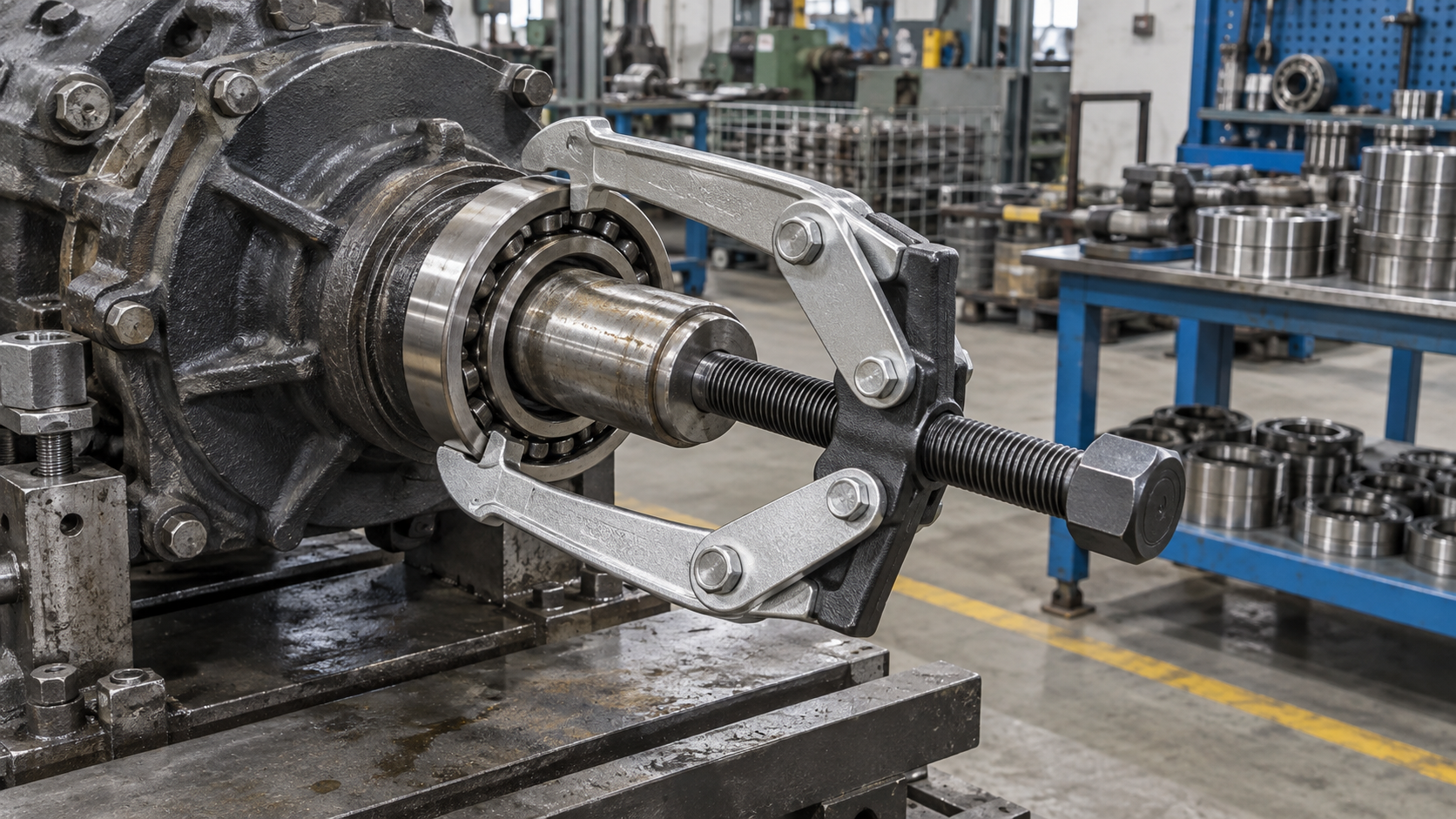
Choose an external puller when jaws can sit behind a firm shoulder and remain centered as force rises. This setup suits many shaft-mounted bearings, hubs, pulleys, gears, and couplings. A two-jaw pattern can enter narrow gaps; a three-jaw pattern often shares load more evenly around a round part. Neither pattern fixes a poor shoulder or a reach that leaves jaw tips barely engaged.
Look for a real shoulder, not a hopeful edge. Buyers should request a drawing or application sketch that shows:
- Minimum and maximum spread across the part.
- Reach from crosshead or jaw pivot to contact point.
- Jaw-tip thickness and entry clearance behind a race or hub.
- Shaft diameter through the forcing-screw path.
- Centering method, jaw locking method, and available reaction area.
A supplier may list a large maximum spread while useful engagement falls sharply near that limit. Ask for working range under full jaw contact. For a service chain, pair the range with a shaft-mounted bearing removal guide so technicians understand when outside jaws should stop and another method should start.
Action recommendation: approve an external model only after a sample drawing shows jaw tips behind a load-bearing shoulder with no seal or cage contact.
External-puller suitability
| Application condition | Suitability | Why | RFQ evidence |
|---|---|---|---|
| Exposed shoulder around a shaft | High | Jaws can seat behind part | Shoulder diameter and photo or sketch |
| Narrow gap behind hub | Conditional | Tip thickness may block entry | Minimum entry gap and tip section |
| Thin stamped cover or seal | Low | Contact may deform the part | Prohibited-contact note |
| Deep offset from crosshead | Conditional | Reach can tilt jaws | Reach drawing and centering detail |
| Three-jaw access around round hub | High when balanced | Load can distribute around circumference | Jaw synchronization or locking detail |
3. When Does an Internal Bearing Puller Make Better Sense?
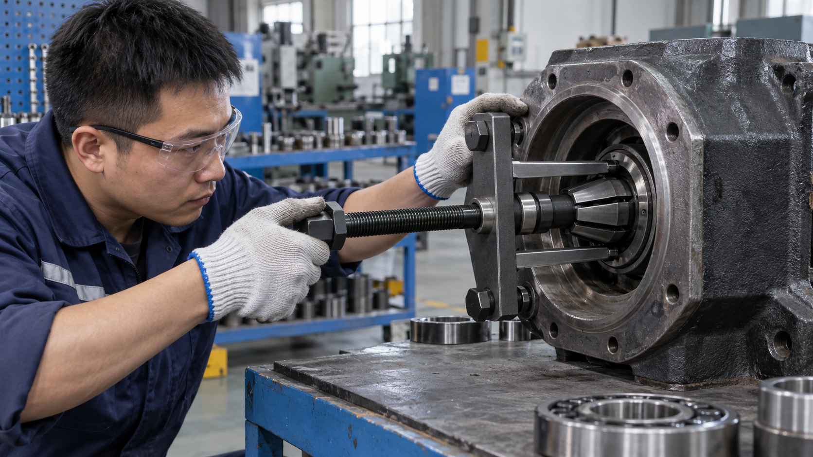
An internal puller makes better sense when a bearing, cup, bush, sleeve, or outer race sits inside a bore with no outside shoulder. Its collet or expanding segments enter the opening, pass the inner lip, and grip from behind. A counter-stay then reacts against a housing face, while a slide hammer supplies repeated axial impacts when a fixed reaction point cannot be used.
The bore decides the tool. Before quoting an internal kit, check:
- Entry bore diameter and usable gripping diameter behind its lip.
- Available grip depth, including chamfer length.
- Wall thickness around a cup or bush.
- Blind depth and clearance for a bridge or hammer.
- Whether an adapter can pass without scraping a seal or machined face.
Segment engagement should sit behind a sound section of part. A collet that touches only a chamfer may release under load. Buyers who sell workshop tools can link a blind-housing puller guide beside product listings, because access mistakes can create poor fit, damaged parts, or tool returns.
Action recommendation: ask for a section-view fit sketch that shows segment expansion behind the part, then reject any kit that depends on a thin chamfer alone.
Internal-puller suitability
| Application condition | Suitability | Why | RFQ evidence |
|---|---|---|---|
| Blind bore with sound rear land | High | Segments can grip behind part | Section view and grip-depth range |
| Open bore with no rear shoulder | Conditional | Collet may push part rather than pull it | Retention method and test piece |
| Thin housing wall | Conditional | Expansion can spread or mark housing | Maximum expansion force guidance |
| Sealed bearing with little rear clearance | Low unless specified | Segments may contact seal or cage | Clearance drawing |
| Bush or sleeve with long bore | High when grip depth matches | Internal contact can stay aligned | Minimum and maximum grip depth |
4. How Should Buyers Measure Bore, Spread, Reach, and Grip Depth?
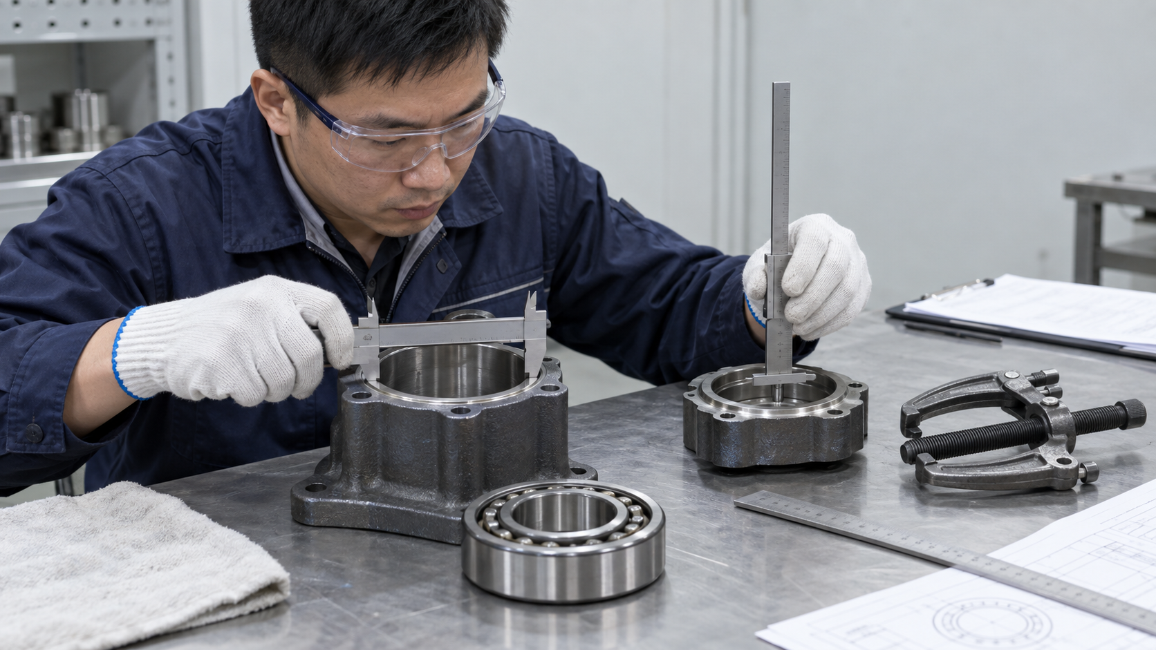
Measurement errors usually come from recording a part’s nominal size while missing the space needed for tool entry. Ask a technician or buyer to measure the actual assembly in its installed state. A bearing catalogue number cannot show a hidden chamfer, shaft shoulder, retaining ring, or offset housing wall.
Measure the obstruction before the tool. Capture these values with a caliper, depth gauge, or simple section sketch:
- Entry bore and actual gripping diameter behind any lip.
- Outside spread across opposite contact points.
- Reach from the puller bridge to the intended grip surface.
- Grip depth available after jaw or segment entry.
- Gap width, shoulder width, shaft diameter, and nearby seal clearance.
Record minimum, typical, and maximum values from real service parts. Working range should sit inside those values with room for centering. A useful bearing puller measurement checklist can turn a return-prone verbal request into a repeatable application record.
Action recommendation: require one annotated application drawing per model, showing every measured value and every surface that must remain untouched.
Measurement-to-specification map
| Field to measure | Why it affects selection | Specification to request | Common mistake |
|---|---|---|---|
| Entry bore | Controls tool insertion | Minimum entry diameter | Using nominal bearing bore |
| Gripping diameter | Controls collet or jaw seat | Working grip range | Quoting catalogue maximum only |
| Spread | Controls external jaw opening | Minimum and maximum spread | Measuring outside housing instead of contact points |
| Reach | Controls bridge and jaw geometry | Working reach at full engagement | Ignoring offset or tilted jaws |
| Grip depth | Controls retention under load | Minimum engagement depth | Relying on chamfer contact |
| Clearance | Protects seal, cage, and wall | Required side and axial clearance | Checking only diameter |
5. How Do Counter-Stays, Slide Hammers, and Forcing Screws Differ?
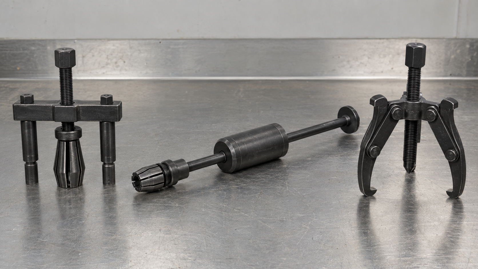
A forcing screw applies controlled axial load through rotation. A counter-stay reacts against a housing face while a screw or spindle draws a gripped part outward. A slide hammer uses moving mass and impact when a broad fixed reaction point cannot be reached. Choice depends on access, part sensitivity, operator control, and adapter compatibility.
Match actuation with reaction space. For procurement and product training, separate these questions:
- Can a bridge or counter-stay sit squarely on a machined face?
- Does a seal, sensor, or light housing tolerate repeated impact?
- Does a forcing screw provide enough travel before bottoming out?
- Do adapters share thread form, shoulder diameter, and load direction?
- Can operators hold alignment while turning or striking?
A screw-driven puller usually gives finer control during a tight fit. A slide hammer can work in a restricted bay yet transmit shock into nearby parts. Hydraulic actuation belongs in a separate specification path; buyers can reference a hydraulic puller selection guide instead of treating every actuator as interchangeable.
Action recommendation: state one approved actuation method for each SKU, then list compatible adapters and prohibited substitutions in the manual.
Actuation selection
| Access or load condition | Preferred method | Main control point | Buyer question |
|---|---|---|---|
| Square housing face available | Counter-stay with forcing screw | Centered reaction and gradual torque | What face diameter and clearance are needed? |
| No fixed reaction face | Slide hammer with internal grip | Impact direction and grip retention | What mass, adapter, and grip limits apply? |
| Sensitive nearby components | Controlled forcing screw | Slow load rise and alignment | What stop-use signs protect seals and walls? |
| Long travel after initial release | Screw or screw-plus-stay | Travel and thread engagement | Does spindle travel cover full removal? |
| Mixed kit with adapters | Specified matched components | Thread, shoulder, and pin fit | Are cross-component substitutions barred? |
6. Which Materials and Manufacturing Details Affect Reliability?
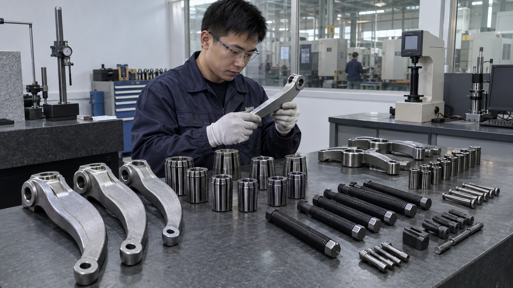
Reliability starts with load-bearing geometry, then depends on material control and fit between moving parts. Arms, collets, bridges, forcing screws, adapters, pins, and locking elements do not share one duty. A supplier should define material and process requirements by component rather than print one vague steel phrase across a catalogue.
Trace the part that carries force. Request evidence for:
- Material grade or approved equivalent for arms, screws, collets, and bridges.
- Heat-treatment route or hardness range where wear and thread damage matter.
- Thread form, flank condition, runout, and engagement length.
- Pin fit, jaw synchronization, and matched-part identification.
- Surface finish on sliding or seating faces, plus corrosion protection.
Do not accept a hardness number without a test method, sample location, and lot reference. Replacement arms or segments should match the original geometry. A puller steel and heat-treatment reference helps buyers ask for process records without inventing a certification claim.
Action recommendation: make component-level material, heat-treatment, thread, and fit checks part of sample approval and change control.
Component QC checks
| Component | Function | QC check | Failure signal |
|---|---|---|---|
| Arms or segments | Transfer grip load | Geometry, surface condition, hardness record | Bending, slippage, uneven contact |
| Bridge or crosshead | Keeps load centered | Flatness, hole position, thread alignment | Tilting or side loading |
| Forcing screw | Creates axial load | Thread profile, straightness, surface finish | Galling, binding, bent spindle |
| Collet or adapter | Fits bore and retains part | Expansion range, shoulder profile, interchange check | Pull-out or bore marking |
| Pins and locks | Hold moving parts | Fit, retention, and visual inspection | Loose arm or sudden release |
7. What Safety Controls Belong in the Product Specification?
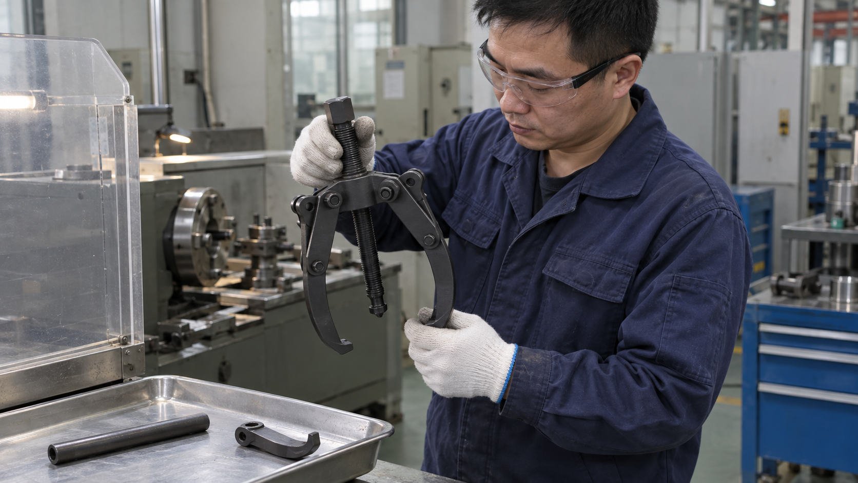
Safety wording should describe actions and limits, not decorate a package. Full engagement, centered loading, rated capacity, guarding, and pre-use inspection all belong in a product specification. Capacity values need a defined basis; buyers should never copy a number from a similar-looking tool without supplier evidence.
Put stop conditions in plain view. A manual, label, or training sheet should tell operators to:
- Check jaws or segments for full, even engagement before loading.
- Keep the spindle, bridge, or hammer aligned with the removal axis.
- Protect hands and nearby people from release movement or falling parts.
- Inspect threads, pins, arms, collets, and adapters before each use.
- Stop when slip, bending, cracking, thread damage, or housing distortion appears.
Improvised cheater bars, welded extensions, mismatched threads, and struck forcing screws can change the load path without warning. A axle bearing puller and slide-hammer comparison helps distributors explain approved impact methods, alignment, and attachment limits.
Action recommendation: ask a supplier to approve the exact safety text and pictograms during sample sign-off, then control revisions with the same discipline as drawings.
Safety evidence
| Safety topic | Minimum evidence to request | Stop-use trigger |
|---|---|---|
| Capacity or load limit | Defined rating basis and application limits | Load exceeds stated limit |
| Engagement | Fit drawing or clear instruction | Jaw or segment sits on an edge only |
| Alignment | Diagram showing axis and reaction face | Tool tilts during loading |
| Inspection | Checklist for threads, pins, arms, and adapters | Cracks, bending, galling, or looseness |
| Improvised parts | Written prohibition and approved component list | Unknown extension or mixed thread |
8. Should Distributors Stock Separate Pullers or Combination Kits?
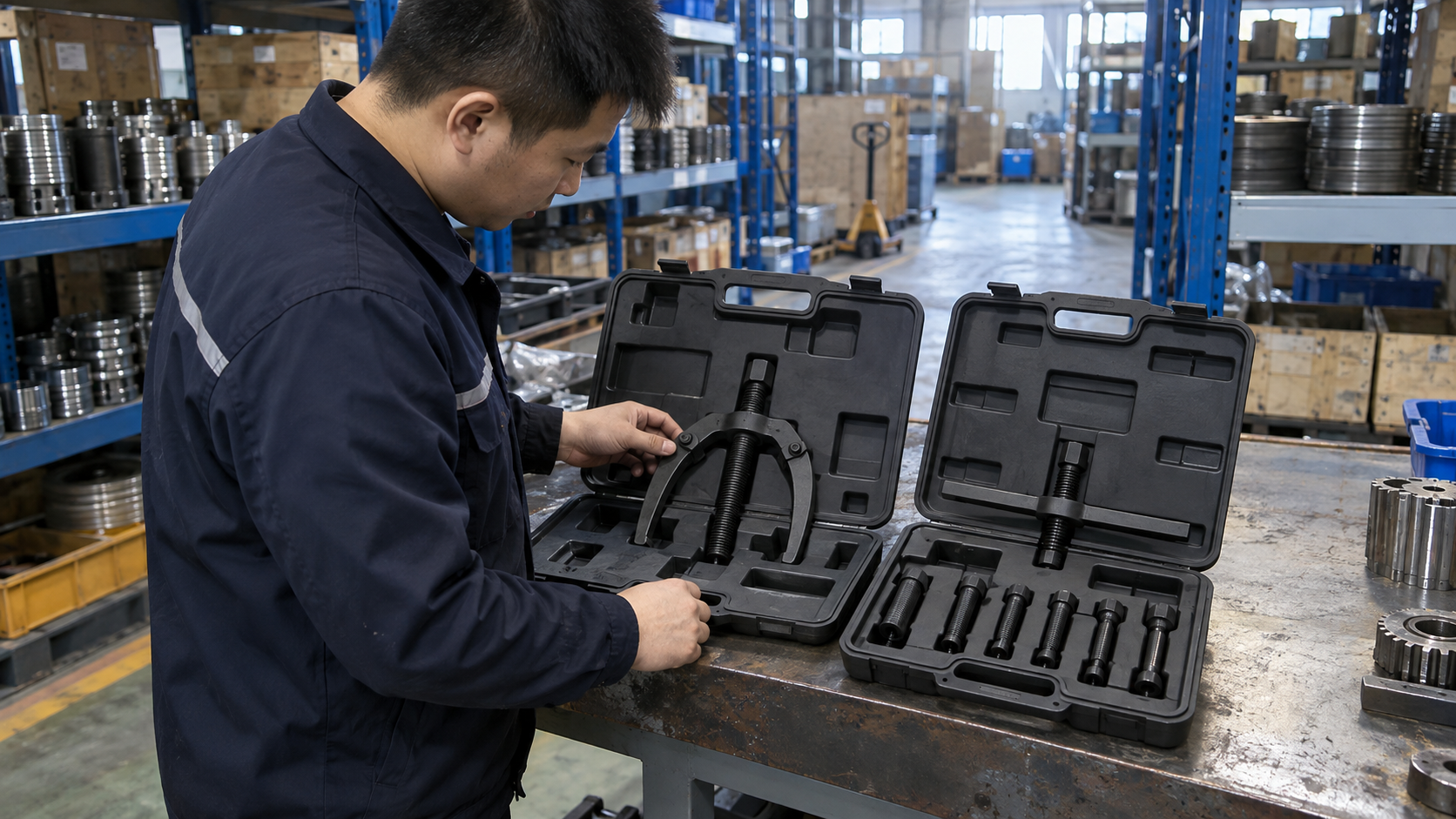
Separate internal and external pullers usually make stock planning clearer when customers face distinct service jobs. A combination kit can cover more applications in one case, yet piece count alone can hide duplicate jaws, missing adapters, or poor overlap between working ranges. Private-label buyers should design assortment around repair tasks rather than chase a larger number printed on a carton.
Count coverage, not loose pieces. Review each proposed assortment against:
- External spread and reach bands that cover common shaft-mounted jobs.
- Internal bore and grip-depth bands for blind housings and sleeves.
- Shared bridges, forcing screws, counter-stays, and adapter families.
- Replacement segments, pins, and wear parts with clear identifiers.
- Case layout that keeps matched components together during replenishment.
Use a coverage matrix before approving a kit. A private-label puller packaging guide can sit near this article when buyers need case layout, labels, manuals, and spare-part planning.
Action recommendation: score each SKU by distinct application coverage and return risk, then remove pieces that add count without adding a usable fit.
Assortment formats
| Stock format | Strength | Risk | Suitable buyer |
|---|---|---|---|
| Single external puller | Clear job and simple replenishment | Limited access coverage | Focused service chain |
| Single internal puller | Good blind-bore coverage | Needs accurate bore data | Specialist workshop supplier |
| Matched internal kit | Shared bridge and several grips | Adapter confusion without labels | Distributor with trained sales staff |
| Internal/external combination kit | Broad job coverage in one case | Higher piece count and overlap | Mobile maintenance team |
| Modular private-label range | Flexible assortment and spares | More SKU and change control work | Importer building a service brand |
9. What Quality-Control Evidence Should Importers Request?
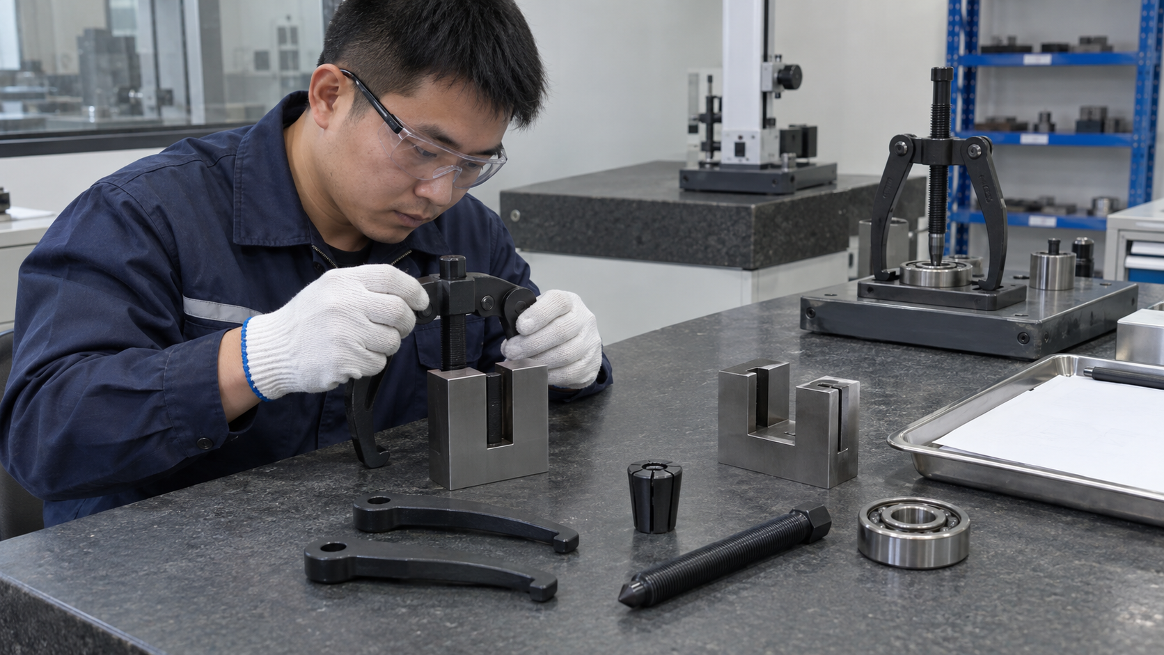
An importer needs more than a pass/fail sample. Request a controlled evidence package that connects drawings, materials, dimensions, function, packaging, and lot traceability. Evidence should match the shipped configuration, including private-label markings, manuals, adapters, and spare parts.
Ask for proof that follows the product. A practical package can include:
- Controlled drawings with revision numbers and critical dimensions.
- Material or process records for specified load-bearing components.
- Dimensional inspection reports tied to sample or production lot.
- Functional checks for grip, travel, thread movement, and component fit.
- Packaging inspection with case layout, labels, manuals, and accessory count.
- Sample approval, deviation records, and a change-notification process.
Do not request a certificate merely because another tool category uses one. Ask what was measured, on which sample, under what method, and how the record connects to a lot. A bearing puller QC document checklist can help purchasing teams standardize supplier submissions.
Action recommendation: make the evidence index part of your purchase order, with revision, lot, sample, and deviation fields completed before release.
Evidence package
| Evidence item | What it should show | Buyer acceptance check |
|---|---|---|
| Approved drawing | Geometry, tolerances, revision, critical surfaces | Matches quoted configuration |
| Material/process record | Component, lot, method, and result | Traceable to supplied part |
| Dimensional report | Actual readings against drawing | Covers grip, reach, spread, and threads |
| Functional record | Grip, travel, alignment, and fit checks | Uses representative assembly |
| Packaging record | Case, labels, manual, and accessory count | Matches approved artwork and packing list |
| Change-control record | Notice and approval path for changes | No unapproved substitute component |
10. How Should Buyers Write the Final RFQ?
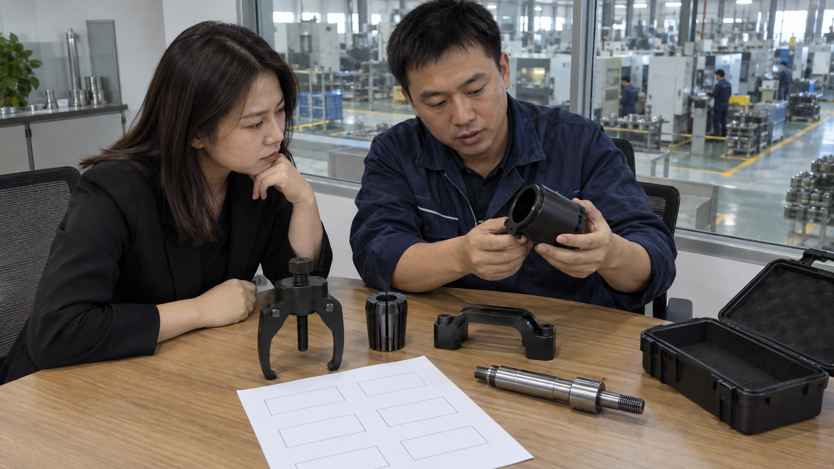
An effective RFQ tells a supplier what must be gripped, where force can react, which dimensions define fit, and what evidence must arrive with samples. It also separates product requirements from packaging preferences. That separation lets a factory price the right assembly instead of guessing from a bearing number.
Write the request around a real removal job. Include:
- Part type, location, material notes, and a photo or section sketch.
- Internal or external grip, working bore or spread, reach, and grip depth.
- Required actuator: forcing screw, counter-stay, slide hammer, or approved alternative.
- Contact surfaces that must remain untouched, such as seals, cages, or housing walls.
- Drawing revision, material/process records, functional checks, packaging, spares, and change control.
State which items remain open for supplier proposal. Do not ask for an unqualified load number, unverified certificate, or broad “universal” claim. For a direct quotation path, place a puller RFQ and contact page after your measurement fields so a supplier can review application drawings before issuing a price.
Action recommendation: send one annotated assembly sketch, one completed measurement table, and one evidence checklist with every RFQ for internal or external bearing pullers.
FAQ 1: Can an external puller remove a bearing from a blind housing?
Usually not. A blind housing removes the outside shoulder needed by external jaws. An internal collet or expanding segment can grip behind an inner lip when bore size, grip depth, and wall strength allow it. Confirm fit with a section drawing before selecting a tool.
FAQ 2: Can an internal puller be used on a shaft-mounted bearing?
Only when a usable bore or inner access point allows safe segment engagement. If a solid shaft blocks internal entry, an external puller may suit the exposed shoulder better. Select by actual contact surface, not by bearing label.
FAQ 3: What measurements are required before selecting an internal puller?
Record entry bore, gripping diameter behind the lip, minimum grip depth, blind depth, chamfer length, wall thickness, and axial clearance. Add a section sketch when a seal, cage, retaining ring, or offset could limit engagement.
FAQ 4: Is a slide hammer safer than a counter-stay puller?
Neither method carries a universal safety advantage. A counter-stay gives gradual screw loading when a square reaction face exists. A slide hammer avoids that face yet adds impact and release movement. Choose the method that preserves alignment and matches the housing, part, and operator controls.
FAQ 5: Should a distributor buy separate internal and external kits?
Buy separate sets when customer jobs and measurements fall into distinct access patterns. Choose a combination kit when matched components cover both patterns without excessive overlap. Compare usable range, spare-part control, case clarity, and return risk rather than piece count alone.
Authoritative references used for technical verification include the SKF bearing-puller catalogue, Schaeffler mounting and dismounting guidance, and OTC puller safety guidelines.
Looking for a reliable mechanic tools manufacturer in China?
If you are sourcing hand tools, socket tools, automotive repair tools, mechanic tool sets or OEM private label tools, contact KOLARWIN Tools for factory-direct quotation, customization support and product consultation.