Need OEM supplier support for this product type?
Contact KOLARWIN Tools for OEM mechanic tools, private label packaging, wholesale quotation and product range support. This gives overseas buyers a clear path from article reading to supplier discussion.
A wheel-bearing job can fail before the part moves. A loose adapter, tilted screw, unsupported hub, or wrong removal method can damage threads, seals, sensors, castings, and the puller. This guide gives distributors, workshop buyers, importers, and private-label tool teams a controlled sequence. It covers preparation, setup, loading, and stopping.
Vehicle service information always controls the exact fastener order, support points, sensor work, torque, replacement parts, and post-repair checks. Use this page as a safe-use framework for a known application. It does not replace a vehicle-specific repair procedure.
Table of contents
- 1. What should you identify before using a wheel bearing puller?
- 2. How should you inspect the puller before setup?
- 3. How do you select the correct puller and adapter?
- 4. How should the force path be aligned?
- 5. How do you set up a mechanical hub or bearing puller?
- 6. When should you use a press kit instead of a puller?
- 7. How should force be applied safely?
- 8. When should you stop the removal attempt?
- 9. How should puller kits be maintained and inspected?
- 10. What should B2B buyers put in a wheel bearing puller RFQ?
1. What Should You Identify Before Using a Wheel Bearing Puller?
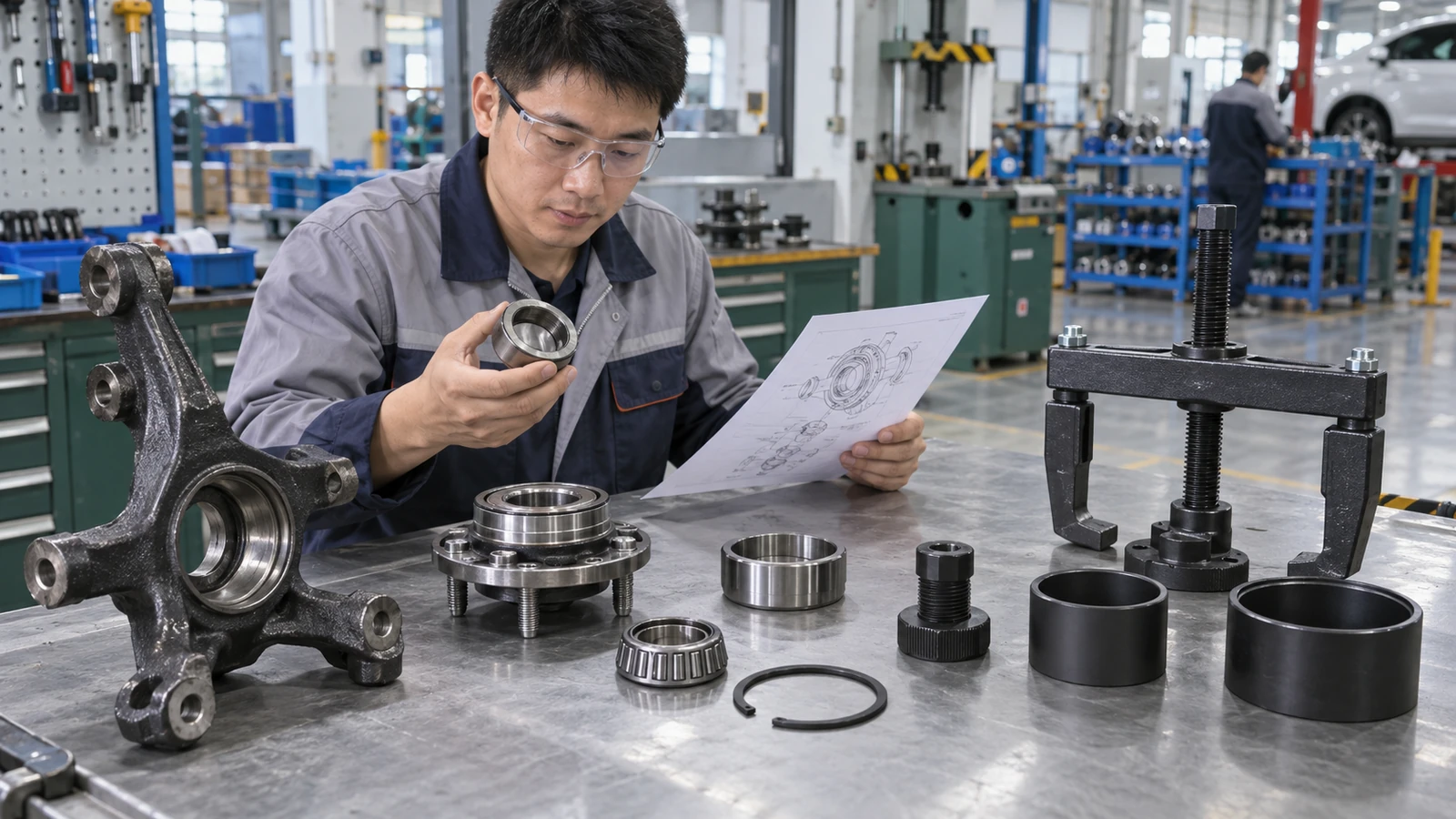
Identify the actual assembly before choosing a tool. “Wheel bearing” may mean a sealed hub unit, a press-in bearing, a separate race, or another wheel-end arrangement. Each design changes which component moves, where reaction force lands, and which nearby parts need protection.
Name each part before choosing a puller. Read current vehicle service information, then record the assembly position, retainers, removal direction, support points, and approved method. Check whether an ABS sensor, tone ring, seal, axle shaft, or thread sits near the force path. Sensor routing and clips can affect this job even when no sensor is targeted.
Record these details:
- vehicle or equipment model and wheel position;
- hub unit, bearing, race, seal, or housing being removed;
- nuts, clips, rings, shields, and fasteners that retain the assembly;
- available gripping and reaction surfaces;
- axle, knuckle, sensor, seal, and thread protection needs;
- approved puller, press, or adapter method.
For wider application context, see KOLARWIN’s automotive repair tools range after the target assembly has been identified.
Practical action: write each target component and reaction surface on a job card before applying force.
Job-identification decision table
| Check | Safe decision | Stop when |
|---|---|---|
| What must move? | Mark the hub, ring, or housing named by the procedure. | The target remains uncertain. |
| What must stay fixed? | Confirm a strong, intended reaction surface. | No supported reaction surface exists. |
| What retains the assembly? | Remove or release each specified retainer. | A clip, ring, or fastener may remain. |
| What needs protection? | Clear or protect sensors, seals, shafts, and threads. | A nearby part enters the load path. |
2. How Should You Inspect the Puller Before Setup?
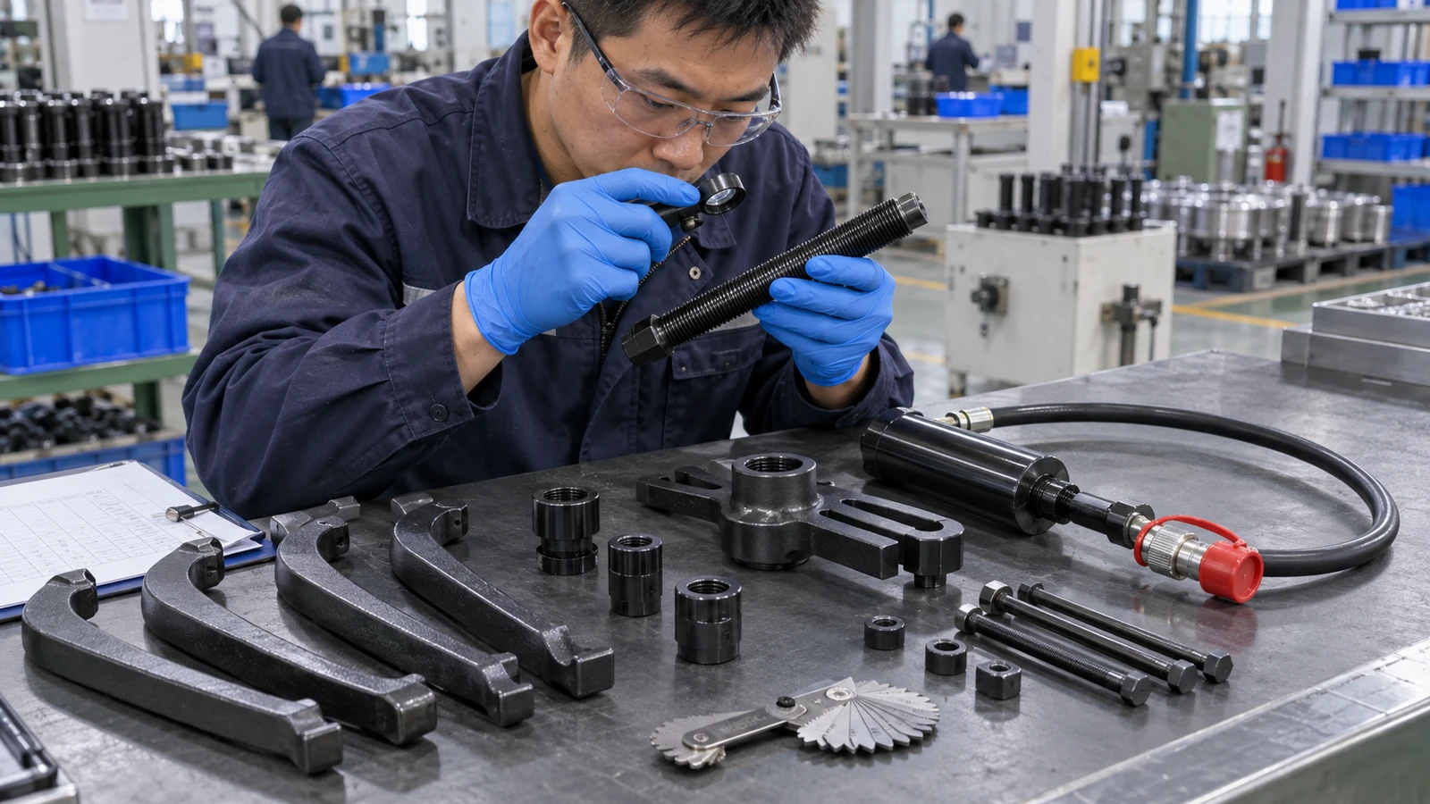
Inspect every load-bearing component before each issue. Check jaws, legs, forcing screws, nuts, pins, bridges, adapters, plates, hydraulic cylinders, hoses, couplers, guards, and case contents. Look for cracks, distortion, mushroomed ends, stripped threads, corrosion, unauthorized welding, leaking seals, and mismatched components.
A questionable component stays out of service. Cleaning cannot restore a bent leg or damaged thread. Use only parts identified as compatible by the tool maker. A signed inspection record helps a workshop or rental fleet show when a kit was checked and why a component was quarantined.
Before setup, confirm:
- tool identity and rated configuration;
- clean contact faces and usable threads;
- even jaw or collet engagement;
- correct adapters and reaction plates;
- sound hydraulic hoses, seals, and couplers where fitted;
- readable warnings and operating instructions;
- complete case contents with no improvised substitutes.
Do not extend a handle or strike a forcing screw unless written tool instructions expressly permit it. Never mix unapproved parts or exceed the stated rating for a configured tool. Lubricate threads only at points and intervals specified by the tool instructions because lubrication changes friction and applied load.
Practical action: attach a signed pre-use checklist to every workshop or rental kit.
Pre-use inspection decision table
| Component | Acceptable condition | Required response |
|---|---|---|
| Forcing screw | Straight, clean, and free from thread damage. | Quarantine any bend, burr, or stripped thread. |
| Jaws or legs | No cracks, spread, distortion, or uneven tips. | Remove the affected part from service. |
| Adapters or plates | Correct geometry with full seating faces. | Select a verified replacement component. |
| Hydraulic system | Dry fittings, sound hose, and secure couplers. | Depressurize and service before reuse. |
3. How Do You Select the Correct Puller and Adapter?
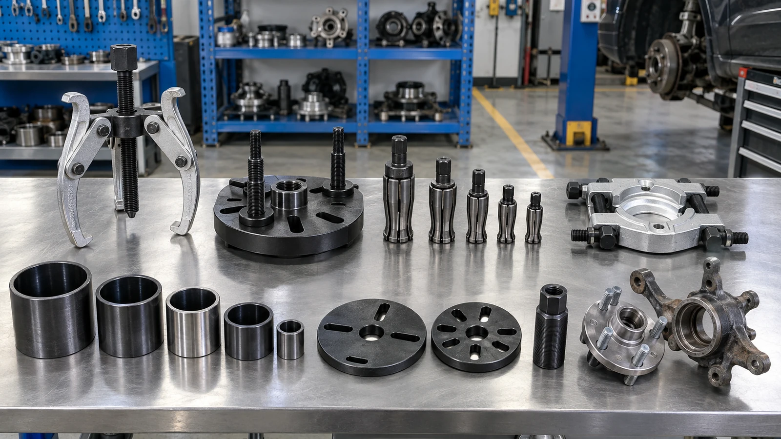
Select from the known access condition and force path. An external jaw needs a secure shoulder. An internal tool needs controlled engagement behind a bore. A hub tool needs compatible flange or stud attachment. A separator or press system may be required when jaw access does not provide a sound load surface.
Fit comes before force. Check spread, reach, bore, thread, bolt pattern, usable depth, adapter seating, and clearance around the axle, knuckle, brake parts, seals, and sensors. A large catalogue range does not prove that a given configuration fits this assembly.
Verify these fields:
- jaw spread and effective reach;
- jaw-tip thickness and seating depth;
- internal engagement behind the bore;
- flange, bolt, or stud compatibility;
- cup and reaction-plate dimensions;
- rated capacity for the selected configuration;
- access for the operating handle, ram, or pump.
Use KOLARWIN’s bearing puller types guide for full family comparison. For measurement fields, see internal versus external puller measurements.
Practical action: approve an application-and-adapter matrix with drawings before listing a kit for sale.
Adapter-fit decision table
| Known condition | Starting check | Safe response |
|---|---|---|
| Exposed shoulder | Full jaw contact behind the target. | Use only when the shoulder supports the intended load. |
| Blind housing | Bore size and rear engagement. | Confirm collet or insert cannot walk out. |
| Hub flange | Stud or bolt pattern and axle clearance. | Use the specified flange attachment. |
| Little rear clearance | Separator, cup, or press support. | Change method when a jaw cannot seat fully. |
4. How Should the Force Path Be Aligned?
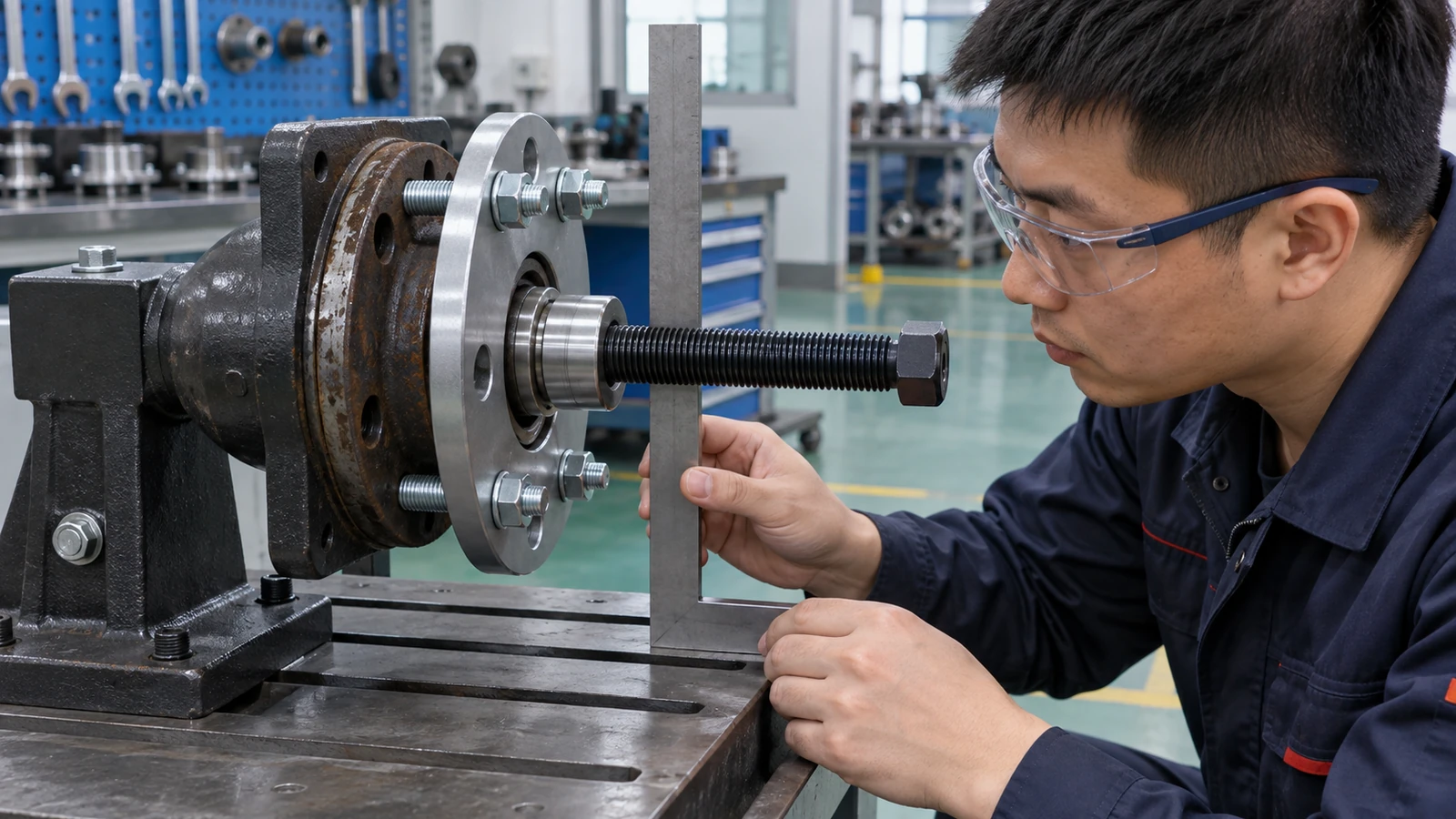
Align each forcing screw, ram, or slide axis with its shaft or bore. Keep reaction surfaces flat, stable, and strong enough for this operation. Protect shaft ends and threads with an approved center point, thrust piece, or adapter. Equal jaw adjustment helps distribute load where the puller design allows it.
Keep every force line straight. A tilted puller can bend a leg, slip from a shoulder, mark a shaft, or release a component suddenly. Re-center the tool whenever contact becomes uneven. Never use a hand as a brace for a loaded jaw.
Review the setup from both sides:
- all jaws or inserts contact the same intended surface;
- the screw or ram sits on the target axis;
- the housing, knuckle, or plate has full support;
- adapters remain square to the hub, ring, or bearing;
- hoses, hands, and fragile parts remain outside the path;
- barriers or blankets are fitted when instructions require them.
Release stored load before repositioning any part. A second person can check alignment visually before a high-force or hydraulic system is loaded.
Practical action: add a two-person alignment sign-off to high-force setup procedures.
Alignment decision table
| Point | Acceptable condition | Unsafe sign |
|---|---|---|
| Jaw contact | Full, even, and behind the intended shoulder. | One jaw catches an edge. |
| Forcing axis | Centered with the shaft or bore. | Screw or ram begins to lean. |
| Reaction support | Flat and fully supported. | Plate rocks or bridges a void. |
| Work area | Clear load path and protected nearby parts. | Hands, hoses, or sensors remain exposed. |
5. How Do You Set Up a Mechanical Hub or Bearing Puller?
Follow the puller instructions and vehicle procedure for this assembly. Support the vehicle or removed component as specified. Remove stated fasteners, clips, and rings. Protect threads, then install approved jaws, flange bolts, cups, or adapters. Hand-tighten evenly, remove slack, and check the force line again before loading.
Stability comes before torque. If a tool shifts while hand-tight, added force will not correct the setup. Stop and select another adapter, support method, or removal system. Keep sensors, seals, brake shields, and unsupported castings outside every load path.
Use this general setup sequence:
- isolate and support the vehicle or assembly under its service procedure;
- remove required retainers and surrounding parts;
- clean accessible contact surfaces;
- install thread or shaft protection;
- seat jaws, flange bolts, cups, or adapters evenly;
- center the forcing screw, ram, or thrust piece;
- turn by hand until slack disappears;
- check support and clearance before applying force.
Use KOLARWIN’s complete mechanic tools checklist for adjacent workshop equipment. That checklist helps buyers plan adjacent hand tools without replacing puller-specific fit checks.
Practical action: photograph one approved setup for each repeat application and attach it to the local work instruction.
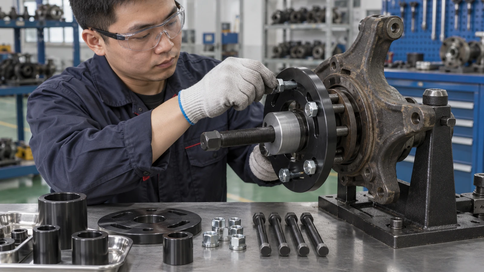
Mechanical setup decision table
| Stage | Verify | Continue only when |
|---|---|---|
| Retainers | Nuts, clips, rings, and bolts. | Required retainers are released. |
| Protection | Shaft end, threads, sensor, and seal. | Approved protectors are seated. |
| Grip | Jaws, studs, flange bolts, or cups. | Contact is complete and balanced. |
| Centering | Screw, ram, target, and reaction side. | The force line remains straight. |
6. When Should You Use a Press Kit Instead of a Puller?
Use a method named by service information for that assembly. An in-place press kit may suit a bearing with matched cups and reaction plates. A workshop press may suit a removed knuckle with stable support. A jaw puller may suit a part with a secure external shoulder. These methods have different load paths and support requirements.
Use support specified for that assembly. Forcing a jaw onto a press-fit bearing without a safe shoulder can damage the housing or tool. Pressing through rolling elements can send load through surfaces that should not carry the operation. Correct ring support depends on each operation. Hub removal, bearing extraction, housing installation, and hub installation can require different contacts.
Compare the procedure against:
- target ring or component being loaded;
- support behind the assembly;
- cup, plate, and adapter dimensions;
- removal or installation direction;
- access for screw, ram, or press bed;
- sensor, seal, thread, and knuckle protection;
- whether the old bearing may separate or be sacrificed.
For a broader product handoff after this decision, use KOLARWIN’s OEM tool product range. It should not replace the application check.
Practical action: list puller, in-place press kit, and workshop press as separate RFQ lines.
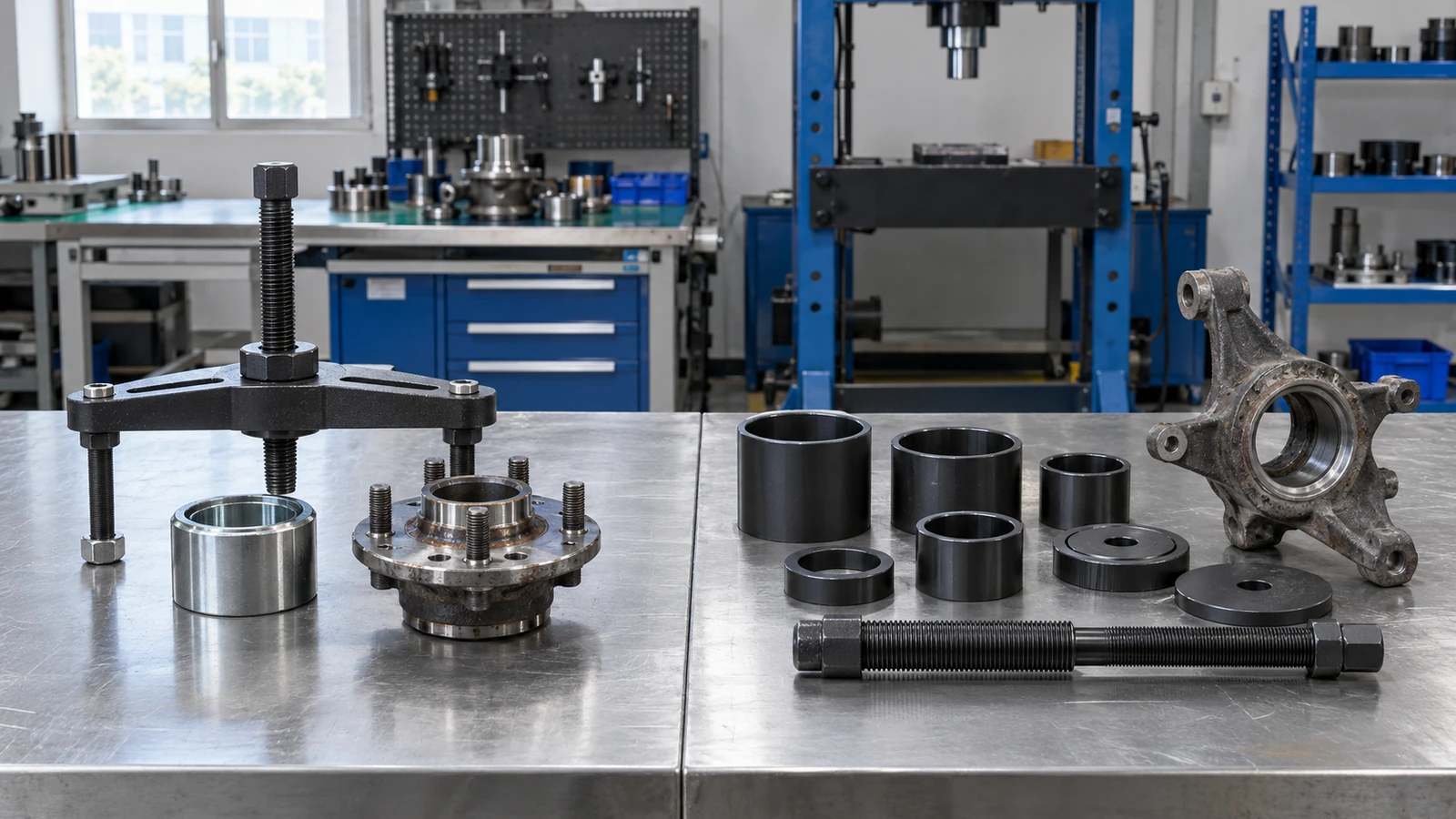
Method decision table
| Method | Starting condition | Main control |
|---|---|---|
| External puller | Secure shoulder behind target. | Full jaw seating and centered screw. |
| Hub puller | Compatible flange or stud attachment. | Pattern, support, and axle protection. |
| In-place press kit | Matched cups and reaction support. | Square cup direction and ring-specific loading. |
| Workshop press | Removed assembly with stable support. | Press-bed support and controlled travel. |
7. How Should Force Be Applied Safely?
Apply force smoothly through an operating method approved for that tool. Keep people outside the likely release path. Watch alignment, contact points, tool deflection, support movement, and part movement. Use guards, barriers, and side-shielded eye protection required by workplace rules and the tool instructions.
Controlled force tells you more than brute force. Rising resistance may signal a remaining retainer, wrong direction, poor support, corrosion, or a mismatched adapter. Stop before the tool rating or component limits are approached. A higher-rated tool cannot correct a bad load path.
During loading:
- keep hands away from jaws, plates, and the target part;
- never search for a hydraulic leak with bare hands;
- use the supplied handle or approved drive method;
- watch for tilting, bending, slipping, or uneven movement;
- stop when the force response changes unexpectedly;
- never exceed the rated configuration;
- never strike or heat the tool unless written instructions permit it;
- release stored load before inspection or adjustment.
An impact drive, added handle, heat, or hammer may be allowed for one tool and prohibited for another. Treat each instruction as application-specific.
Practical action: train operators to stop on abnormal resistance rather than push through it.
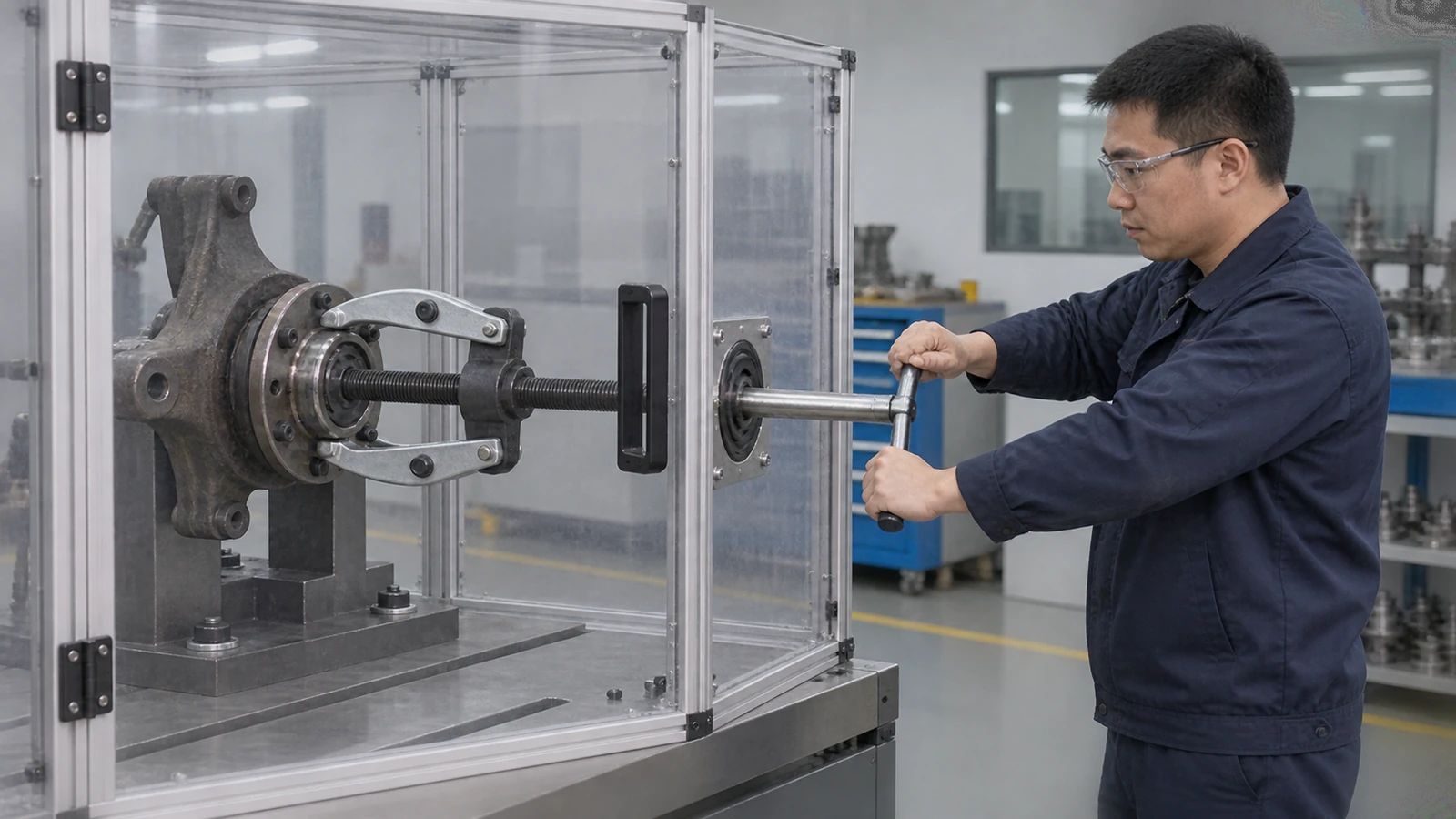
Loading-control decision table
| Observation | Possible meaning | Response |
|---|---|---|
| Smooth centered movement | Setup may be functioning. | Continue while monitoring. |
| Jaw begins to walk | Grip or alignment is unstable. | Release load and reset. |
| Screw or leg bends | Overload or misalignment. | Stop, unload, and quarantine the part. |
| No movement with rising force | Retainer, corrosion, support, or method issue. | Stop and reassess. |
8. When Should You Stop the Removal Attempt?
Stop when the tool slips, bends, leaks, cracks, binds, tilts, or makes an unexpected sound. Stop when a workpiece deforms, any reaction plate shifts, a sensor or seal enters the path, or force rises without controlled movement. Do not reposition a loaded system.
A safe stop protects the whole assembly. Release stored energy under an approved procedure, then inspect tool and workpiece. Escalate through service information, another method, or qualified technical support when causes remain unclear.
Stop for any of these signs:
- visible tool, adapter, plate, or casting deformation;
- damaged or stripping threads;
- hydraulic leakage or hose movement;
- uneven jaw engagement;
- shifting supports or reaction plates;
- unexpected cracking, distortion, or wrong-component movement;
- unclear remaining retention;
- force that approaches the configuration rating without movement.
Do not add extra force, strike a tool, or keep pumping while its cause remains unknown. A controlled reset costs less than an uncontrolled release or damaged assembly.
Practical action: print stop conditions on kit packaging, instructions, rental checklists, and operator training cards.
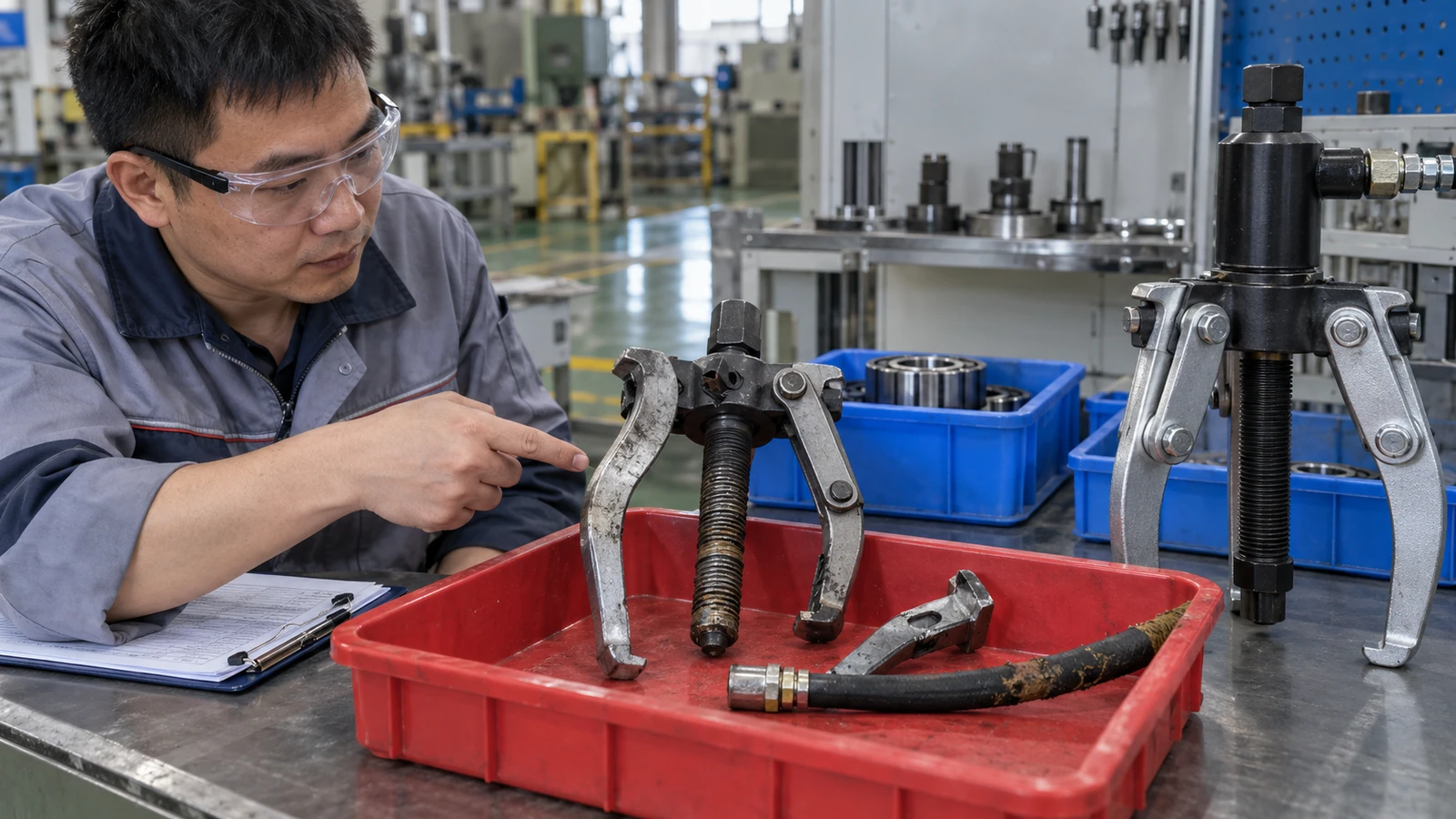
Stop-condition decision table
| Warning sign | Immediate action | Next decision |
|---|---|---|
| Tool deformation | Release load safely. | Quarantine and replace the affected part. |
| Hydraulic leak | Depressurize from a safe position. | Service the system under its instructions. |
| Workpiece moves incorrectly | Stop operation. | Recheck target, support, and force path. |
| No controlled movement | Do not add extra force. | Check retainers, corrosion, method, and rating. |
9. How Should Puller Kits Be Maintained and Inspected?
Clean components after use and store them in an organized case or rack. Protect threads and machined contact surfaces from dirt and corrosion. Inspect wear parts after abnormal loading and at defined intervals. Replace parts only with approved components that preserve the original load path.
A complete kit protects the process. Missing adapters encourage improvisation. Mixed parts can create an incompatible force path. A case layout should make missing items visible before a job begins.
Track these maintenance points:
- cleaning and corrosion protection;
- forcing-screw, jaw, leg, plate, and adapter condition;
- hydraulic hose, coupler, cylinder, and seal condition;
- lubrication at approved points only;
- inventory and replacement-part control;
- quarantine and repair records;
- readable ratings, warnings, and instructions;
- case layout and application labels.
For packaged workshop programs, review KOLARWIN’s mechanics tool set configurations after defining the puller kit contents. Use that page for storage and private-label planning after service controls are defined.
Practical action: assign each kit an ID and record inspections, missing parts, repairs, and abnormal-load events.

Maintenance decision table
| Record field | Purpose | Trigger |
|---|---|---|
| Kit identity | Tracks one complete system. | Issue, return, or transfer. |
| Component inspection | Finds wear and damage. | Scheduled check or abnormal load. |
| Quarantine history | Prevents unsafe reuse. | Overload, leak, crack, or defect. |
| Replacement record | Preserves compatibility. | Missing or worn adapter. |
10. What Should B2B Buyers Put in a Wheel Bearing Puller RFQ?
A buyer-ready RFQ describes the application, interfaces, approved configurations, evidence, packaging, and spare parts. Ask for drawings and an application matrix instead of buying by jaw count, case size, or a broad range label. Request proof that the selected adapter seats fully and leaves sensors, seals, shafts, and threads clear.
Write the RFQ around evidence. Include vehicle or equipment categories, target component, grip and reaction surfaces, dimensions, removal direction, and force method. Add rated configurations, operating limits, instructions, warnings, inspection methods, spare routes, and sample-fit requirements. If a tool deliberately loads an old bearing, state that outcome. A buyer should not expect removed parts to remain reusable.
Include these fields:
- vehicle or equipment application and wheel position;
- hub, bearing, race, housing, or seal outcome;
- spread, reach, bore, thread, bolt-pattern, and adapter dimensions;
- rated capacity by approved configuration;
- load-path drawing with support and sensor clearance;
- material or heat-treatment evidence where the specification requires it;
- component markings, warnings, and operating manual;
- replacement parts, seals, and repair route;
- case layout, labels, sample approval, and inspection plan.
For supplier review after puller requirements are fixed, use KOLARWIN’s OEM automotive-tool supplier evaluation. Keep supplier questions tied to this wheel-bearing application.
Practical action: approve the drawing, application list, sample, instructions, and case contents before mass production. For a controlled inquiry, request a wheel-bearing puller quotation with those files attached.
FAQ: Can one wheel bearing puller fit every vehicle?
No single configuration fits every vehicle or wheel-end design. Hub architecture, bearing arrangement, access, bolt pattern, sensor position, and service instructions vary. Treat any broad range statement as a starting point that still requires application and sample verification.
FAQ: Should you use an impact wrench on a puller forcing screw?
Only use an impact wrench when the puller maker explicitly approves that drive method for this configuration. Otherwise use the supplied handle or specified operating method. A vehicle procedure may impose a separate restriction even when a tool instruction allows a particular drive.
FAQ: Can you add a pipe to the puller handle for more force?
Do not add an extension unless written tool instructions expressly permit it. Extra force can overload a screw, leg, adapter, or attachment without giving the operator a reliable load indication.
FAQ: What should you do if the bearing does not move?
Stop and release stored energy using the approved method. Recheck retainers, direction, target component, adapter seating, support, alignment, corrosion, tool choice, and configuration rating. Ask qualified technical support when service information does not resolve an obstruction.
FAQ: What is the main safety check?
Confirm a straight, fully supported force path with complete tool engagement before applying load. Keep people outside the likely release path, protect nearby sensors and seals, and watch for any change in alignment or tool condition.
Looking for a reliable mechanic tools manufacturer in China?
If you are sourcing hand tools, socket tools, automotive repair tools, mechanic tool sets or OEM private label tools, contact KOLARWIN Tools for factory-direct quotation, customization support and product consultation.