Home/Blog/ Gear Puller vs Bearing Puller: A B2B Buyer Guide

Gear Puller vs Bearing Puller: A B2B Buyer Guide

Get OEM Tool Catalog + Quote Back to Tool Sourcing Blog
Gear puller and bearing puller samples compared in a Chinese tool factory
This KOLARWIN Tools article is written for overseas distributors, wholesalers, importers and private label tool brands sourcing mechanic tools, automotive repair tools, socket tools, hand tools and OEM tool sets from China. Use this guide to compare product options, check supplier quality points and move from reading to a faster B2B inquiry.

Need OEM supplier support for this product type?

Contact KOLARWIN Tools for OEM mechanic tools, private label packaging, wholesale quotation and product range support. This gives overseas buyers a clear path from article reading to supplier discussion.

A gear puller and a bearing puller can look almost identical in a catalogue. Both may use two or three jaws around a part while a centre screw pushes on a shaft. The names still matter because the workpiece, gripping surface, and acceptable damage are different. This guide helps distributors, importers, and private-label buyers specify the complete pulling setup instead of ordering by product name alone.

1. What is the difference between a gear puller and a bearing puller?
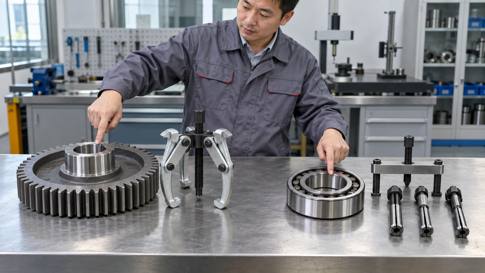
Gear puller and bearing puller samples compared in a Chinese tool factory

A gear puller normally removes a gear, pulley, sprocket, coupling, or similar hub-mounted component from a shaft. A bearing puller is selected around the bearing’s location and the ring that can be gripped: an outside shoulder, internal bore, inner ring, or hub.

The categories overlap. One reversible jaw puller may remove either component, while a blind-bearing collet, separator, or hub plate is more specialized. Treat the names as starting labels, then specify engagement, reaction, reach, spread, and actuation.

A serviceable gear may need to survive removal. A bearing may be discarded while the shaft and housing remain usable. State that outcome before comparing tools.

KOLARWIN’s automotive repair tools range provides the broader product context. Attach a marked RFQ photo or drawing that identifies the moving part, protected surfaces, grip point, and screw reaction point.

Gear puller vs bearing puller at a glance

Buyer field Gear puller Bearing puller What the RFQ must settle
Typical target Gear, pulley, sprocket, coupling, or hub Bearing, race, bush, or hub assembly Exact component and part condition
Common engagement External jaws behind a strong hub or shoulder Jaws, internal collet, separator, bridge, or flange plate Surface that carries the pull
Reuse priority Often preserve the removed component May preserve or discard the bearing Parts that must remain undamaged

2. What does a gear puller remove, and where should it grip?
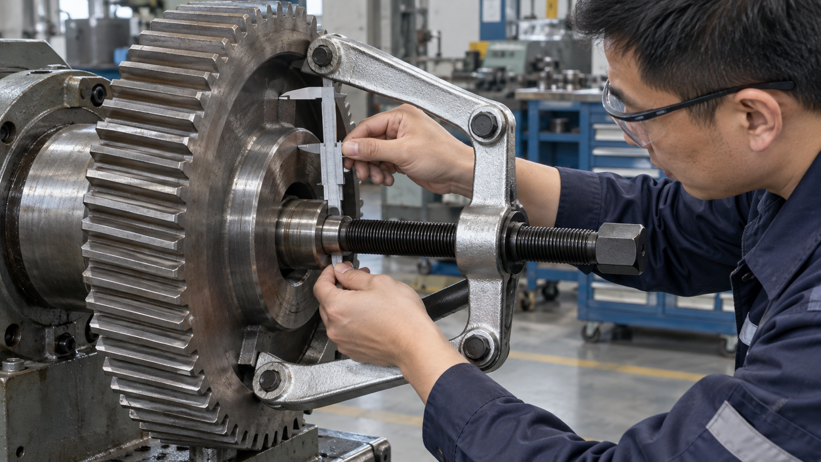
Chinese engineer checking a gear puller beside a gear with a strong hub

A gear puller works best when every jaw reaches behind a strong, continuous shoulder close to the gear hub. The centre screw reacts on the shaft end, so the jaws and screw must share one axis. Pulling on tooth tips, thin webs, decorative flanges, or an unsupported rim can bend or crack the component before the hub moves.

Record hub diameter, width, distance to the gripping face, rear clearance, shaft-end shape, and nearby obstructions. Long jaws may flex more and reduce usable capacity. Maximum spread does not guarantee enough reach at that spread.

If hooks cannot enter the rear gap, the job may need a separator, flange, or bolt attachment. “Universal gear puller” should never replace a configuration drawing.

For adjacent jaw choices, use the 2-jaw versus 3-jaw puller guide. Reject sample photographs that show the jaws loaded on gear teeth rather than a supported hub or shoulder.

Gear-removal fit check

Measurement Why it matters Evidence to request
Rear clearance Decides whether jaw hooks or a separator can enter Dimensioned side view and fit photo
Reach to grip face Determines whether the jaws can seat behind the hub Reach at the required spread
Shaft-end condition Affects screw centring and surface protection Approved tip or protective centre adaptor
Hub strength Confirms where pulling load may be applied Component drawing or sample test

3. What does a bearing puller remove, and which ring should carry the load?
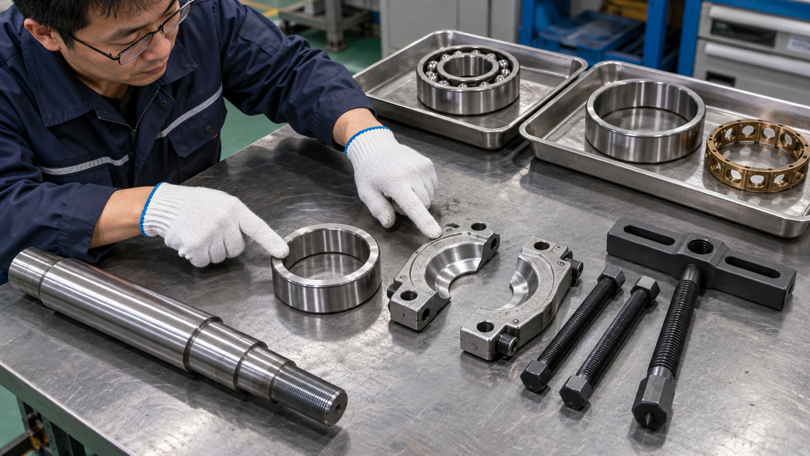
Bearing inner ring separator and bridge components arranged for removal planning

A bearing puller may remove a complete bearing, an inner ring left on a shaft, an outer ring inside a housing, or a hub-bearing assembly. Those jobs need different gripping systems. External jaws need an exposed shoulder. Internal collets need a bore and a sound rear edge. A separator closes behind a ring when normal hooks are too thick. A hub kit may react through a bridge, flange, or service fixture.

When a bearing must remain usable, follow its work instruction and avoid routing removal force through rolling elements, a principle also described in NASA bearing-maintenance guidance. If it is scrap, the shaft, housing, seal seat, sensor area, and adjacent machined faces may still need protection.

The bearing separator versus bearing puller comparison explains how a separator creates a gripping edge. The bearing-race puller guide covers ring-specific selection. Put “target ring” and “protected components” in separate RFQ fields.

Bearing-removal interface check

Bearing condition Likely interface Buyer concern
Exposed bearing on shaft External jaws or separator behind inner ring Shoulder depth and shaft protection
Bearing inside blind housing Expanding collet with bridge or slide hammer Bore range and rear engagement
Outer race in accessible housing Internal puller or dedicated attachment Housing support and release path
Hub-bearing assembly Flange, plate, screw, or hydraulic fixture Vehicle fit, studs, sensors, and adapters

4. Why do gear pullers and bearing pullers overlap in catalogues?
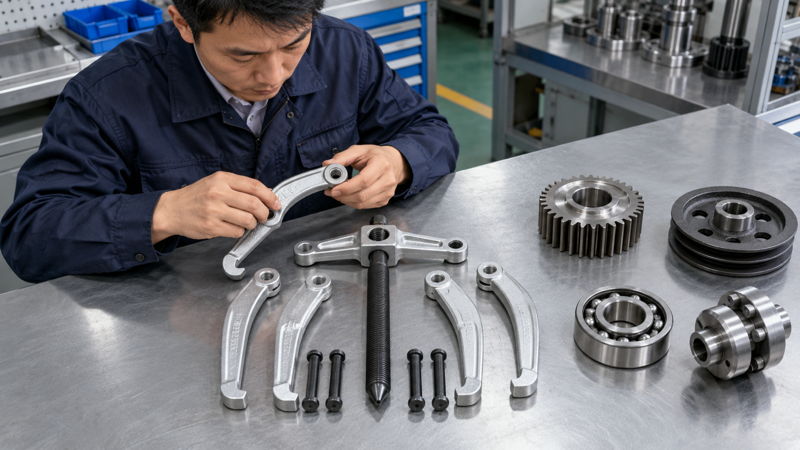
Reversible puller parts reviewed beside gears bearings pulleys and couplings

Many pullers are classified by construction rather than workpiece. A U.S. military hand-tool manual describes overlapping gear-and-bearing-puller uses. A reversible jaw tool can grip gears, pulleys, bearings, and couplings with suitable shoulders. A separator can support a bearing ring or thin gear hub. A slide hammer describes force delivery; its attachment decides what it grips.

A supplier may list one frame under “gear and bearing puller.” That does not prove universal fit. Jaw direction, hook geometry, spindle length, adaptor thread, and rating can change.

Buyers can use the types of bearing pullers selection guide to separate jaw, hub, hydraulic, and slide-hammer families. Quote each approved configuration by part number and drawing revision.

Where the categories overlap

Puller design Possible targets Required verification
Reversible jaw puller Gear, pulley, exposed bearing, coupling Grip face, jaw direction, reach, spread, rating
Separator plus bridge Bearing ring, thin gear hub, small pulley Plate seating, rod spacing, frame compatibility
Slide hammer with adapters Internal bearing, hub, seal, axle attachment Adapter thread, impact approval, release zone
Hydraulic jaw frame Large gear, bearing, pulley, coupling Complete-system pressure and force limits

5. How do grip, reach, spread, and reaction decide the correct puller?
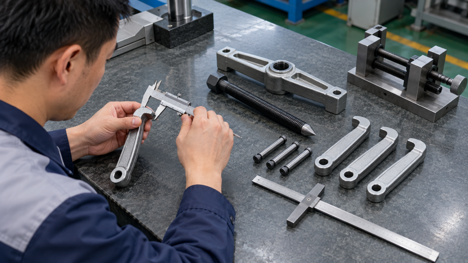
Chinese metrology engineer measuring unloaded puller jaws and centre screw

Grip is the held surface. Reach is the distance from frame to grip. Spread is the opening at working reach. Reaction is where the screw, bridge, cylinder, or fixture pushes.

These four fields must work together. A wide puller may not reach a recessed gear; a long one may lack spread. A collet may match the bore but lack a rear lip. A centred screw can still damage a hollow, threaded, or soft shaft end without the correct adaptor.

Measure minimum, typical, and maximum service parts. Add clearance, obstructions, and removal travel. Show the load path from reaction point to every gripping element.

For internal and external interfaces, compare the internal versus external bearing puller guide. Require a range chart that pairs reach and spread instead of listing two independent maximum values.

Puller sizing fields

Field Minimum useful record Common purchasing error
Grip Surface, width, depth, and condition Naming only the outside diameter
Reach Distance to the seated jaw or plate Assuming maximum reach works at maximum spread
Spread or bore range Working minimum and maximum by setup Treating one headline range as universal
Reaction Shaft end, bridge feet, or fixture face Ignoring strength, alignment, or protection
Travel Distance needed to release the fit Selecting a screw or stroke that stops early

6. When can one puller kit cover both gears and bearings?
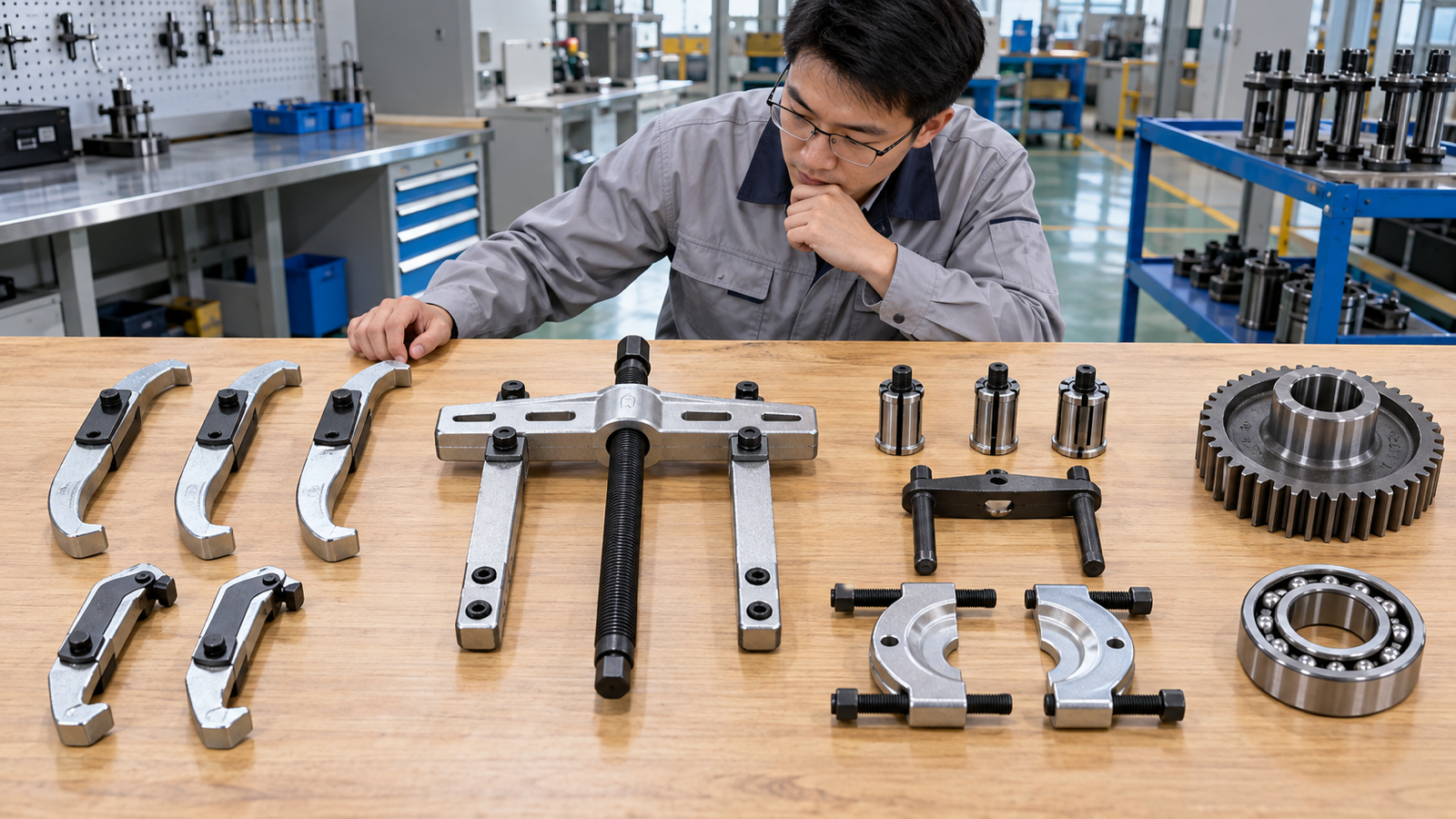
Modular puller frame external jaws internal collets and separator attachments

One frame can serve both jobs when its screw, yoke, jaws, working range, and rating match each approved setup. This is common where both targets present a strong external shoulder and the same centred shaft-end reaction. The shared frame does not make every attachment interchangeable.

A gear may need longer external jaws or a flange attachment. An exposed bearing may use the same jaws, while a tight inner ring needs a separator and a blind bearing needs an internal collet. Hollow or threaded shaft ends can also require a different reaction adaptor.

List every approved assembly in the kit BOM. Give the shared frame, jaws, separator, collets, bridge, tips, and adapters separate part identities. The blind-hole bearing puller guide explains why bore access needs its own attachment and validation.

Shared-frame decision matrix

Kit element When it can be shared When it must change
Yoke or frame Range and rating cover both setups Reach, spread, or load path falls outside approval
Centre screw and tip Shaft-end reaction is compatible Shaft is hollow, threaded, soft, or differently centred
External jaws Both targets have sound accessible shoulders Grip depth, hook thickness, or reach differs
Separator or internal collet Only for its validated interface Gear hub, bearing ring, or bore needs another attachment

7. Should the pulling force be mechanical, hydraulic, or impact-based?
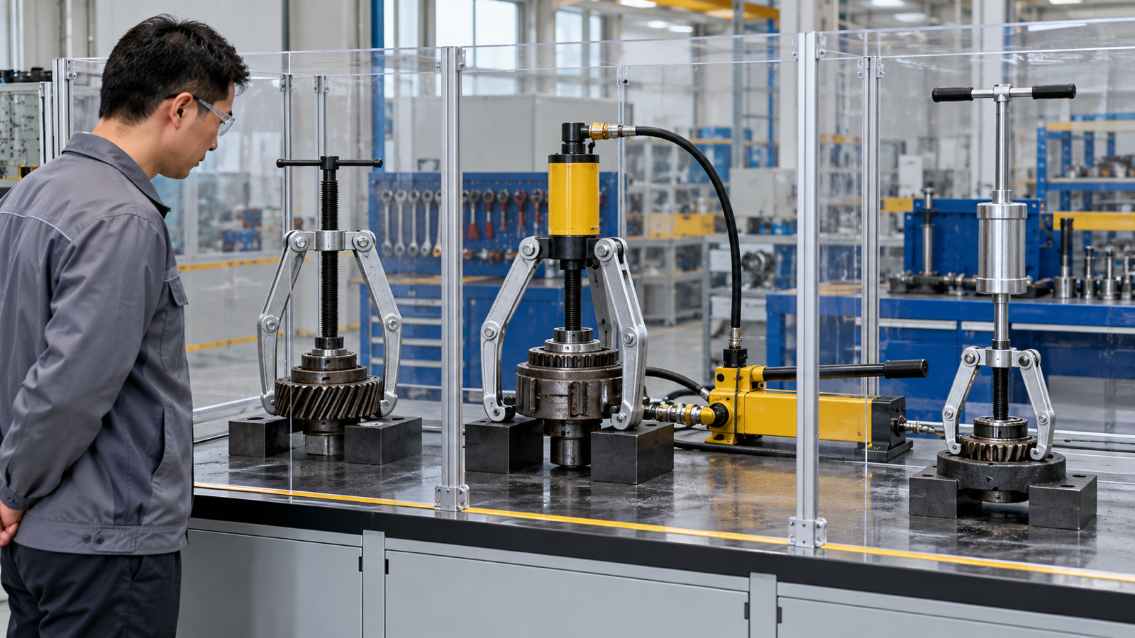
Mechanical hydraulic and slide hammer puller systems in a guarded test area

A mechanical forcing screw gives gradual movement. It needs sound threads, specified lubrication, a compatible hand drive, and centred reaction. An improvised pipe extension or unapproved impact wrench can overload the frame or spindle.

A hydraulic system reduces operator effort. Its pump, hose, couplers, cylinder, frame, jaws, plates, and adapters form one load-bearing system. Request pressure limits, configuration-specific force data, inspection criteria, and controlled spares. A cylinder rating alone does not rate the puller.

A slide hammer applies repeated impulse. Check attachment, working space, connection, mass, stroke, and release path. A stuck component alone does not justify switching force methods.

Compare actuation choices in the mechanical versus hydraulic bearing pullers guide, and use the axle puller versus slide hammer guide for impact attachments. Approve the attachment and force method as one configuration.

Actuation comparison

Force method Procurement advantage Control point
Mechanical screw Simple setup and gradual movement Thread condition, drive method, centring, rated setup
Hydraulic Higher force with lower manual effort Pressure, hose/coupler condition, complete-system rating
Slide hammer Useful where an axial impact attachment is specified Adapter retention, stroke space, release path, impact limit

8. What damage and safety risks should a buyer control?
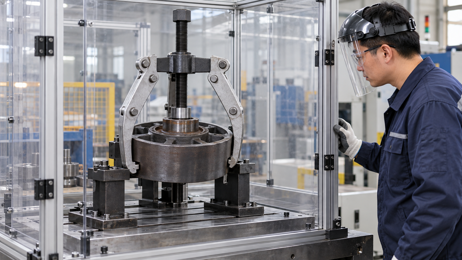
Chinese safety engineer inspecting a guarded gear puller test setup

Poor contact causes hooks to roll off, thin webs to bend, plates to cant, collets to expand on the wrong surface, or screws to walk off-axis. Released components and broken tool parts can move suddenly. Support heavy parts independently.

The Canadian Centre for Occupational Health and Safety advises users to select the correct size, inspect pullers for wear or cracks, secure the workpiece, keep the screw aligned, maintain firm jaw contact, apply even pressure, and stop if the puller deforms. Its gear-puller safety guidance also warns against heating or grinding a puller and against using air-powered tools on it.

Workplace procedures still govern isolation and stored energy. For covered U.S. general-industry servicing, OSHA’s hazardous-energy rule addresses unexpected start-up or stored-energy release. OSHA’s U.S. construction hand-tool rule requires unsafe tools to be kept out of use in its scope.

Require instructions that define inspection, PPE, guarding or containment, support, exclusion zone, approved drive method, and stop conditions.

Puller risk-control record

Risk Purchase control Operator stop condition
Jaw or plate slips Fit test and full-contact photograph Wobble, uneven seating, or movement at the grip
Puller deforms Configuration-specific rating and inspection criteria Bent frame, stretched jaw, damaged pin, or thread distress
Component releases suddenly Independent support and clear release zone Support cannot control the freed part
Stored energy or machine motion Site isolation procedure and competent setup Energy cannot be isolated or verified

9. What QC evidence and RFQ fields should importers request?
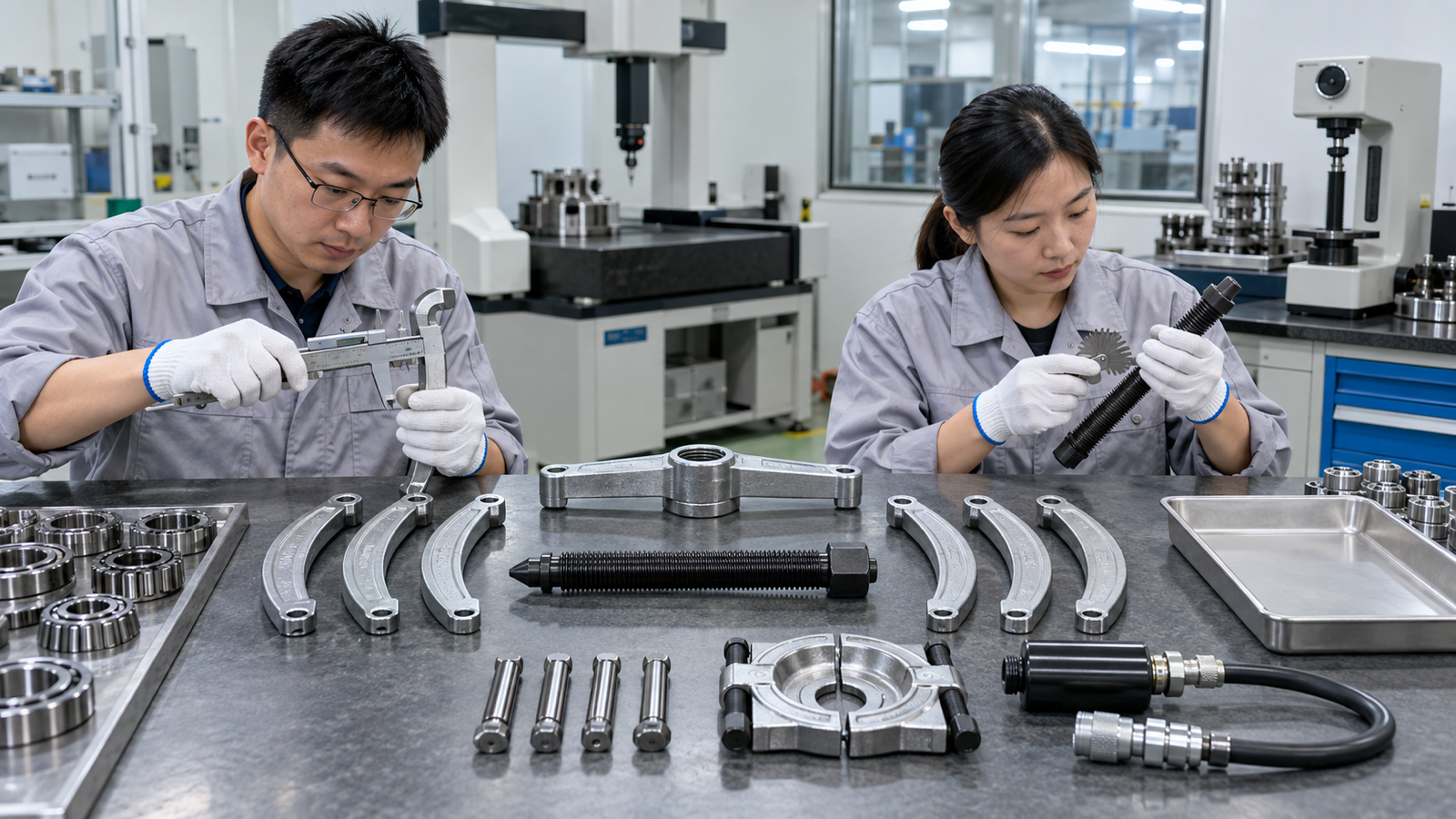
Chinese factory inspectors checking puller jaws threads pins and separator parts

The approval package should connect the drawing, bill of materials, heat-treatment route, critical dimensions, functional test, and package contents. Replace “industrial grade” with evidence that production matches the approved configuration.

Inspect jaw symmetry, hook geometry, alignment, pins, spindle thread, drive end, collet taper, separator faces, and hydraulic connections. Agree on gauges, sampling, limits, and records before production. Document the test fixture, load path, and stop condition.

The RFQ should name target parts, dimension range, protected surfaces, actuation, configurations, rating basis, finish, markings, spares, case layout, instructions, and market requirements. Replacement jaws, screws, tips, pins, seals, and adapters need controlled part identities.

Approve a golden sample and signed inspection drawing together; either one alone leaves room for unrecorded changes.

Puller RFQ checklist

RFQ block Required information Approval evidence
Application Target component, photos, dimensions, reuse requirement Marked drawing and fit test
Tool configuration Grip, reach, spread, reaction, actuation Assembly drawing and BOM
Performance Rating basis, test method, stop condition Traceable sample or lot record
Quality control Critical dimensions, material/process records, sampling Inspection report and golden sample
Commercial package Kit contents, spares, case, manual, private label Sealed sample and change-control list

10. How should a distributor choose and approve the final puller range?
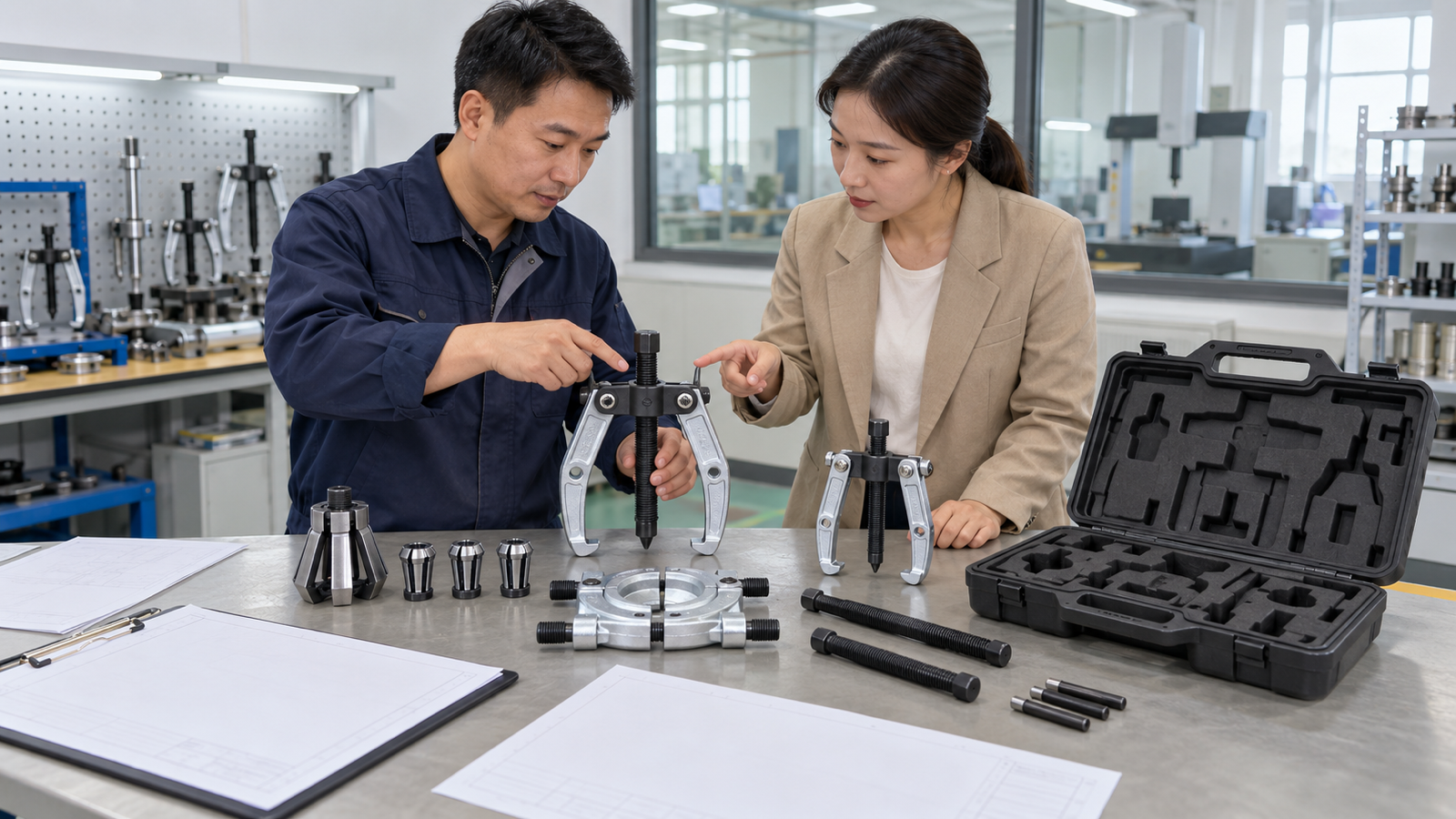
Chinese supplier and buyer approving OEM gear and bearing puller samples

Start with customer jobs, not piece count. Group applications by external shoulder, narrow rear gap, blind bore, flange attachment, and required force. Assign a verified configuration to each group.

For every SKU, record the component, grip, protected parts, working range, actuation, rating, spares, and package contents. Test the deepest reach, narrowest clearance, or least forgiving reaction surface. Keep photos and inspection records with the revision.

When the application sheet is complete, contact KOLARWIN for an OEM puller-tool quotation with market, quantity, dimensions, kit layout, spares, and private-label requirements.

Approve only when the drawing, sample, load path, instructions, and package describe the same setup.

Q1: Can a gear puller remove a bearing? Yes, when the bearing has an accessible shoulder and the jaws, reach, spread, reaction, and rating match the job.

Q2: Can a bearing puller remove a gear? Some can, if they grip a supported gear hub or shoulder. Do not pull on teeth or a thin web unless the component procedure permits it.

Q3: Is a three-jaw puller always better than a two-jaw puller? No. Three jaws can improve centring; two may fit tighter access. Grip, reach, spread, alignment, and rating decide.

Q4: What measurements should a buyer send with a puller RFQ? Send diameter, bore, rear clearance, grip width, reach, spread, shaft-end detail, removal travel, obstructions, protected surfaces, and weight.

Q5: What is the safest way to describe a universal puller set? List every approved configuration and range. Do not imply that one capacity, adapter, or force method covers every component.

Looking for a reliable mechanic tools manufacturer in China?

If you are sourcing hand tools, socket tools, automotive repair tools, mechanic tool sets or OEM private label tools, contact KOLARWIN Tools for factory-direct quotation, customization support and product consultation.
A gear puller and a bearing puller can look almost identical in a catalogue. Both may use two or three jaws around a part while a centre screw pushes on a shaft. The names still matter because the workpiece, gripping surface, and acceptable damage are different. This guide helps distributors, importers, and private-label buyers specify the complete pulling setup instead of ordering by product name alone.

1. What is the difference between a gear puller and a bearing puller?

Gear puller and bearing puller samples compared in a Chinese tool factory

A gear puller normally removes a gear, pulley, sprocket, coupling, or similar hub-mounted component from a shaft. A bearing puller is selected around the bearing’s location and the ring that can be gripped: an outside shoulder, internal bore, inner ring, or hub.

The categories overlap. One reversible jaw puller may remove either component, while a blind-bearing collet, separator, or hub plate is more specialized. Treat the names as starting labels, then specify engagement, reaction, reach, spread, and actuation.

A serviceable gear may need to survive removal. A bearing may be discarded while the shaft and housing remain usable. State that outcome before comparing tools.

KOLARWIN’s automotive repair tools range provides the broader product context. Attach a marked RFQ photo or drawing that identifies the moving part, protected surfaces, grip point, and screw reaction point.

Gear puller vs bearing puller at a glance

Buyer field Gear puller Bearing puller What the RFQ must settle
Typical target Gear, pulley, sprocket, coupling, or hub Bearing, race, bush, or hub assembly Exact component and part condition
Common engagement External jaws behind a strong hub or shoulder Jaws, internal collet, separator, bridge, or flange plate Surface that carries the pull
Reuse priority Often preserve the removed component May preserve or discard the bearing Parts that must remain undamaged

2. What does a gear puller remove, and where should it grip?

Chinese engineer checking a gear puller beside a gear with a strong hub

A gear puller works best when every jaw reaches behind a strong, continuous shoulder close to the gear hub. The centre screw reacts on the shaft end, so the jaws and screw must share one axis. Pulling on tooth tips, thin webs, decorative flanges, or an unsupported rim can bend or crack the component before the hub moves.

Record hub diameter, width, distance to the gripping face, rear clearance, shaft-end shape, and nearby obstructions. Long jaws may flex more and reduce usable capacity. Maximum spread does not guarantee enough reach at that spread.

If hooks cannot enter the rear gap, the job may need a separator, flange, or bolt attachment. “Universal gear puller” should never replace a configuration drawing.

For adjacent jaw choices, use the 2-jaw versus 3-jaw puller guide. Reject sample photographs that show the jaws loaded on gear teeth rather than a supported hub or shoulder.

Gear-removal fit check

Measurement Why it matters Evidence to request
Rear clearance Decides whether jaw hooks or a separator can enter Dimensioned side view and fit photo
Reach to grip face Determines whether the jaws can seat behind the hub Reach at the required spread
Shaft-end condition Affects screw centring and surface protection Approved tip or protective centre adaptor
Hub strength Confirms where pulling load may be applied Component drawing or sample test

3. What does a bearing puller remove, and which ring should carry the load?

Bearing inner ring separator and bridge components arranged for removal planning

A bearing puller may remove a complete bearing, an inner ring left on a shaft, an outer ring inside a housing, or a hub-bearing assembly. Those jobs need different gripping systems. External jaws need an exposed shoulder. Internal collets need a bore and a sound rear edge. A separator closes behind a ring when normal hooks are too thick. A hub kit may react through a bridge, flange, or service fixture.

When a bearing must remain usable, follow its work instruction and avoid routing removal force through rolling elements, a principle also described in NASA bearing-maintenance guidance. If it is scrap, the shaft, housing, seal seat, sensor area, and adjacent machined faces may still need protection.

The bearing separator versus bearing puller comparison explains how a separator creates a gripping edge. The bearing-race puller guide covers ring-specific selection. Put “target ring” and “protected components” in separate RFQ fields.

Bearing-removal interface check

Bearing condition Likely interface Buyer concern
Exposed bearing on shaft External jaws or separator behind inner ring Shoulder depth and shaft protection
Bearing inside blind housing Expanding collet with bridge or slide hammer Bore range and rear engagement
Outer race in accessible housing Internal puller or dedicated attachment Housing support and release path
Hub-bearing assembly Flange, plate, screw, or hydraulic fixture Vehicle fit, studs, sensors, and adapters

4. Why do gear pullers and bearing pullers overlap in catalogues?

Reversible puller parts reviewed beside gears bearings pulleys and couplings

Many pullers are classified by construction rather than workpiece. A U.S. military hand-tool manual describes overlapping gear-and-bearing-puller uses. A reversible jaw tool can grip gears, pulleys, bearings, and couplings with suitable shoulders. A separator can support a bearing ring or thin gear hub. A slide hammer describes force delivery; its attachment decides what it grips.

A supplier may list one frame under “gear and bearing puller.” That does not prove universal fit. Jaw direction, hook geometry, spindle length, adaptor thread, and rating can change.

Buyers can use the types of bearing pullers selection guide to separate jaw, hub, hydraulic, and slide-hammer families. Quote each approved configuration by part number and drawing revision.

Where the categories overlap

Puller design Possible targets Required verification
Reversible jaw puller Gear, pulley, exposed bearing, coupling Grip face, jaw direction, reach, spread, rating
Separator plus bridge Bearing ring, thin gear hub, small pulley Plate seating, rod spacing, frame compatibility
Slide hammer with adapters Internal bearing, hub, seal, axle attachment Adapter thread, impact approval, release zone
Hydraulic jaw frame Large gear, bearing, pulley, coupling Complete-system pressure and force limits

5. How do grip, reach, spread, and reaction decide the correct puller?

Chinese metrology engineer measuring unloaded puller jaws and centre screw

Grip is the held surface. Reach is the distance from frame to grip. Spread is the opening at working reach. Reaction is where the screw, bridge, cylinder, or fixture pushes.

These four fields must work together. A wide puller may not reach a recessed gear; a long one may lack spread. A collet may match the bore but lack a rear lip. A centred screw can still damage a hollow, threaded, or soft shaft end without the correct adaptor.

Measure minimum, typical, and maximum service parts. Add clearance, obstructions, and removal travel. Show the load path from reaction point to every gripping element.

For internal and external interfaces, compare the internal versus external bearing puller guide. Require a range chart that pairs reach and spread instead of listing two independent maximum values.

Puller sizing fields

Field Minimum useful record Common purchasing error
Grip Surface, width, depth, and condition Naming only the outside diameter
Reach Distance to the seated jaw or plate Assuming maximum reach works at maximum spread
Spread or bore range Working minimum and maximum by setup Treating one headline range as universal
Reaction Shaft end, bridge feet, or fixture face Ignoring strength, alignment, or protection
Travel Distance needed to release the fit Selecting a screw or stroke that stops early

6. When can one puller kit cover both gears and bearings?

Modular puller frame external jaws internal collets and separator attachments

One frame can serve both jobs when its screw, yoke, jaws, working range, and rating match each approved setup. This is common where both targets present a strong external shoulder and the same centred shaft-end reaction. The shared frame does not make every attachment interchangeable.

A gear may need longer external jaws or a flange attachment. An exposed bearing may use the same jaws, while a tight inner ring needs a separator and a blind bearing needs an internal collet. Hollow or threaded shaft ends can also require a different reaction adaptor.

List every approved assembly in the kit BOM. Give the shared frame, jaws, separator, collets, bridge, tips, and adapters separate part identities. The blind-hole bearing puller guide explains why bore access needs its own attachment and validation.

Shared-frame decision matrix

Kit element When it can be shared When it must change
Yoke or frame Range and rating cover both setups Reach, spread, or load path falls outside approval
Centre screw and tip Shaft-end reaction is compatible Shaft is hollow, threaded, soft, or differently centred
External jaws Both targets have sound accessible shoulders Grip depth, hook thickness, or reach differs
Separator or internal collet Only for its validated interface Gear hub, bearing ring, or bore needs another attachment

7. Should the pulling force be mechanical, hydraulic, or impact-based?

Mechanical hydraulic and slide hammer puller systems in a guarded test area

A mechanical forcing screw gives gradual movement. It needs sound threads, specified lubrication, a compatible hand drive, and centred reaction. An improvised pipe extension or unapproved impact wrench can overload the frame or spindle.

A hydraulic system reduces operator effort. Its pump, hose, couplers, cylinder, frame, jaws, plates, and adapters form one load-bearing system. Request pressure limits, configuration-specific force data, inspection criteria, and controlled spares. A cylinder rating alone does not rate the puller.

A slide hammer applies repeated impulse. Check attachment, working space, connection, mass, stroke, and release path. A stuck component alone does not justify switching force methods.

Compare actuation choices in the mechanical versus hydraulic bearing pullers guide, and use the axle puller versus slide hammer guide for impact attachments. Approve the attachment and force method as one configuration.

Actuation comparison

Force method Procurement advantage Control point
Mechanical screw Simple setup and gradual movement Thread condition, drive method, centring, rated setup
Hydraulic Higher force with lower manual effort Pressure, hose/coupler condition, complete-system rating
Slide hammer Useful where an axial impact attachment is specified Adapter retention, stroke space, release path, impact limit

8. What damage and safety risks should a buyer control?

Chinese safety engineer inspecting a guarded gear puller test setup

Poor contact causes hooks to roll off, thin webs to bend, plates to cant, collets to expand on the wrong surface, or screws to walk off-axis. Released components and broken tool parts can move suddenly. Support heavy parts independently.

The Canadian Centre for Occupational Health and Safety advises users to select the correct size, inspect pullers for wear or cracks, secure the workpiece, keep the screw aligned, maintain firm jaw contact, apply even pressure, and stop if the puller deforms. Its gear-puller safety guidance also warns against heating or grinding a puller and against using air-powered tools on it.

Workplace procedures still govern isolation and stored energy. For covered U.S. general-industry servicing, OSHA’s hazardous-energy rule addresses unexpected start-up or stored-energy release. OSHA’s U.S. construction hand-tool rule requires unsafe tools to be kept out of use in its scope.

Require instructions that define inspection, PPE, guarding or containment, support, exclusion zone, approved drive method, and stop conditions.

Puller risk-control record

Risk Purchase control Operator stop condition
Jaw or plate slips Fit test and full-contact photograph Wobble, uneven seating, or movement at the grip
Puller deforms Configuration-specific rating and inspection criteria Bent frame, stretched jaw, damaged pin, or thread distress
Component releases suddenly Independent support and clear release zone Support cannot control the freed part
Stored energy or machine motion Site isolation procedure and competent setup Energy cannot be isolated or verified

9. What QC evidence and RFQ fields should importers request?

Chinese factory inspectors checking puller jaws threads pins and separator parts

The approval package should connect the drawing, bill of materials, heat-treatment route, critical dimensions, functional test, and package contents. Replace “industrial grade” with evidence that production matches the approved configuration.

Inspect jaw symmetry, hook geometry, alignment, pins, spindle thread, drive end, collet taper, separator faces, and hydraulic connections. Agree on gauges, sampling, limits, and records before production. Document the test fixture, load path, and stop condition.

The RFQ should name target parts, dimension range, protected surfaces, actuation, configurations, rating basis, finish, markings, spares, case layout, instructions, and market requirements. Replacement jaws, screws, tips, pins, seals, and adapters need controlled part identities.

Approve a golden sample and signed inspection drawing together; either one alone leaves room for unrecorded changes.

Puller RFQ checklist

RFQ block Required information Approval evidence
Application Target component, photos, dimensions, reuse requirement Marked drawing and fit test
Tool configuration Grip, reach, spread, reaction, actuation Assembly drawing and BOM
Performance Rating basis, test method, stop condition Traceable sample or lot record
Quality control Critical dimensions, material/process records, sampling Inspection report and golden sample
Commercial package Kit contents, spares, case, manual, private label Sealed sample and change-control list

10. How should a distributor choose and approve the final puller range?

Chinese supplier and buyer approving OEM gear and bearing puller samples

Start with customer jobs, not piece count. Group applications by external shoulder, narrow rear gap, blind bore, flange attachment, and required force. Assign a verified configuration to each group.

For every SKU, record the component, grip, protected parts, working range, actuation, rating, spares, and package contents. Test the deepest reach, narrowest clearance, or least forgiving reaction surface. Keep photos and inspection records with the revision.

When the application sheet is complete, contact KOLARWIN for an OEM puller-tool quotation with market, quantity, dimensions, kit layout, spares, and private-label requirements.

Approve only when the drawing, sample, load path, instructions, and package describe the same setup.

Q1: Can a gear puller remove a bearing? Yes, when the bearing has an accessible shoulder and the jaws, reach, spread, reaction, and rating match the job.

Q2: Can a bearing puller remove a gear? Some can, if they grip a supported gear hub or shoulder. Do not pull on teeth or a thin web unless the component procedure permits it.

Q3: Is a three-jaw puller always better than a two-jaw puller? No. Three jaws can improve centring; two may fit tighter access. Grip, reach, spread, alignment, and rating decide.

Q4: What measurements should a buyer send with a puller RFQ? Send diameter, bore, rear clearance, grip width, reach, spread, shaft-end detail, removal travel, obstructions, protected surfaces, and weight.

Q5: What is the safest way to describe a universal puller set? List every approved configuration and range. Do not imply that one capacity, adapter, or force method covers every component.

Why Partner with Kolarwin Tools?

Factory-Direct Pricing Skip the middleman — access competitive wholesale prices and protect your margins
Private Label & OEM Ready Your brand, our expertise — full customization from logo to packaging
Fast Global Shipping Reliable delivery to 60+ countries with full export documentation support
Low MOQ, High Flexibility Start small, scale fast — flexible order quantities to fit your business
Dedicated B2B Support One-on-one account management from quote to delivery, every time

Get Your Free Quote in 24 Hours

Tell us your sourcing needs — we'll respond with a tailored quote, product specs, and the best pricing for your market. No commitment required.

Chat on WhatsApp Email Us Directly