Need OEM supplier support for this product type?
Contact KOLARWIN Tools for OEM mechanic tools, private label packaging, wholesale quotation and product range support. This gives overseas buyers a clear path from article reading to supplier discussion.
Manual deburring tools remove raised material left by cutting, drilling, or machining. A hand tool can suit an accessible hole edge, straight edge, curved edge, or tube end when its blade matches the workpiece. It should not substitute for a drawing-defined chamfer or a repeatable CNC process without a sample and acceptance check.
1. What does a manual deburring tool do?
A manual deburring tool holds a cutting blade, scraper, countersink, or other working element so an operator can remove a burr from a chosen feature. A burr is raised or displaced material left at an edge after a process such as drilling, milling, turning, shearing, or sawing. Its size and shape depend on the operation and material, so “deburr” alone is not a complete process instruction.
The objective may be to remove a sharp projection, clear a hole entrance, or prepare an edge for assembly. Those outcomes differ from cutting a specified chamfer or changing a part’s dimensions. NOGA’s product range separates swivel blades, countersinks, scrapers, specialty tools, and machine tools; each family has its own intended features and limits.
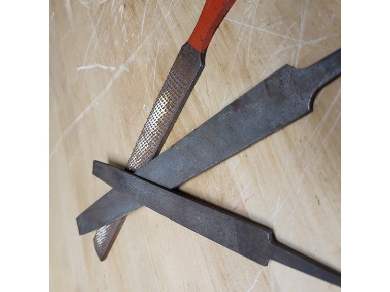
Start by naming the feature and required result. A broad explanation of hand file types can help when a file, rather than a dedicated deburring blade, suits the task.
- Identify how the burr was created.
- Locate the exact edge, hole, or surface that needs attention.
- State whether the goal is burr removal, edge break, or a dimensioned chamfer.
- Select a tool by maker-documented application and workpiece material.
Define the work before selecting a tool
| Question | Example detail to record | Why it matters |
|---|---|---|
| Burr source | Drilled hole, sawn edge, milled pocket | Different features need different access and cutting geometry |
| Feature | Hole mouth, cross-hole, straight edge, tube end | Tool reach and blade shape must suit the feature |
| Material | Grade or reliable material description | Blade material and geometry are not universal |
| Required result | Remove loose burr, protect fit, or meet a chamfer callout | Prevents uncontrolled material removal |
2. When is a hand deburring tool a good fit?
A handheld tool can suit localized burrs where an operator can see or otherwise inspect the target feature and guide the tool in a controlled way. Examples include a single outside edge, an accessible drilled-hole entrance, or a short run around a cut tube end. Work volume, part geometry, surface sensitivity, and required repeatability influence the decision.
Manual work also leaves more variation between people and strokes than a defined machine cycle can. That does not make every hand operation unsuitable; it means the acceptance method and process instruction should match the quality requirement. NOGA’s catalog lists both manual systems and CNC-oriented tools, showing that deburring has distinct equipment categories.
Use the hand tool only where access and inspection are clear. If an edge sits inside an inaccessible passage or part-to-part consistency is critical, assess a dedicated process and confirm it with the responsible engineer.
- Use a hand process for a defined, reachable feature.
- Confirm the operator can control blade contact without touching adjacent surfaces.
- Define visual, tactile-instrument, or dimensional inspection without bare-finger checks.
- Escalate inaccessible or high-repeatability features for process review.
Hand process fit check
| Condition | Hand-tool fit | Buyer action |
|---|---|---|
| Local, accessible edge | Potentially suitable | Trial the exact blade and handle on sample stock |
| Hidden cross-hole or deep feature | Uncertain | Verify reach and blade application; define inspection method |
| Repeated feature with tight consistency need | May need more process control | Compare a fixture or engineered machine process |
| Drawing-controlled edge geometry | Requires controlled removal | Set measurement and approval criteria before work |
3. Which edges can a manual deburring tool address?
Manual swivel-blade systems may be offered for straight edges, curved edges, holes, cross-holes, and deep holes. NOGA describes these application groups for its 2.6 mm light-duty and 3.2 mm heavy-duty swivel-blade programs. Those labels describe a product range, not proof that every blade in the range reaches every feature.
On a straight edge, the operator must keep the cutting element on the burr without digging into the parent surface. A curved edge adds changing contact geometry. A hole entrance requires a blade shape and reach suited to the bore. A cross-hole or deep hole may need a specialized profile and confirmation that the tool can reach the burr without damaging the bore or nearby surface.
Read the application drawing for the specific blade. NOGA advises selection by workpiece material and dimensions and notes that application illustrations show where a blade works. Its catalog includes other edge tools as well, so do not assume all deburring handles or blades interchange.
- Distinguish outside edge from internal edge.
- Record curvature, bore diameter, depth, and nearby surfaces.
- Check application diagrams for the exact blade.
- Confirm handle, holder, and blade compatibility before ordering.
Feature and access match
| Feature | Selection question | Common limitation |
|---|---|---|
| Straight edge | Can the blade track the full edge length? | Blade may lift or gouge if angle changes |
| Curved edge | Does the blade geometry follow the radius? | A general blade may not track the curve |
| Hole or cross-hole | Is the burr accessible at the right edge? | Not every blade reaches or clears an intersection |
| Deep feature | Does the tool reach without contacting protected surfaces? | Reach alone does not confirm suitable cutting geometry |
4. How do you deburr a drilled hole by hand?
A drilled hole may leave a raised lip at its entrance, exit, or intersection with another bore. A manual tool can address an accessible edge when its maker identifies the blade for that geometry and material. Keep through-hole front and back edges distinct from cross-hole intersections; their access paths differ.
Choose a blade and holder by pilot-hole size, burr location, workpiece material, and required edge result. NOGA’s blade guidance describes hole, cross-hole, and deep-hole use across product families, while its separate UBURR system is designed for automatic front-and-back deburring of drilled through-holes in a machine cycle. That distinction helps buyers avoid treating a generic hand blade as an all-feature solution.
Confirm the contact path before production. Use a representative sample, inspect the bore and adjacent surfaces, and compare the result with the drawing or approved sample. If a specified chamfer is required, measure it with the agreed method.
- Identify which hole edge carries the burr.
- Verify blade geometry and reach against the exact hole.
- Protect the bore and nearby precision surfaces.
- Record the resulting edge condition before approving the method.
For dimensional checking, the digital caliper vs dial caliper guide covers measuring-tool selection; use a suitable method for the actual chamfer tolerance.
Hole-edge selection record
| Feature data | Record | Confirmation needed |
|---|---|---|
| Hole | Diameter, depth, through or blind | Tool reach and blade path |
| Burr position | Entry, exit, cross-hole intersection | Which edge is accessible |
| Material | Grade and condition | Blade suitability |
| Edge requirement | Burr removal or specified geometry | Inspection and measurement method |
5. What should you check when deburring straight or curved edges?
Before contacting the edge, decide which side carries the burr and which surfaces must remain untouched. A straight edge can still vary in thickness or have changing burr height. On a curved edge, the blade’s contact point moves as the radius changes; an unsuitable geometry can slip onto the face or remove more material than intended.
Hand deburring should remove the raised material required by the process. It should not round over a sharp functional corner, alter a sealing face, or erase a controlled dimension unless the drawing or work instruction allows that change. On a surface with a coating or finish, confirm whether contact is acceptable and test a sample.
Let the drawing set the edge condition. If the drawing only says “break edge,” ask engineering for an allowable range or approved reference before turning that phrase into a guessed chamfer size.
- Identify the burr side and protected surfaces.
- Check whether coating, sealing, or fit depends on the edge.
- Control tool contact and inspect after a short trial.
- Use a dimensioned requirement where the edge affects function.
When a cutting operation creates the burr, review its setup too. The how to use a hacksaw guide covers hand-saw operation; this guide addresses only the resulting edge.
Edge condition and acceptance
| Requirement | Hand-deburring consideration | Acceptance evidence |
|---|---|---|
| Remove sharp projection | Avoid disturbing adjacent face | Defined visual inspection or approved sample |
| Preserve a functional corner | Limit contact to the burr | Drawing note or process instruction |
| Protect finish or coating | Trial on representative surface | Sample approval and inspection record |
| Chamfer to dimension | Control amount removed | Suitable gauge or measurement plan |
6. How should you approach a cut tube end?
A cut tube end presents at least two edges: an outside lip and an inside lip. Wall thickness, tube material, diameter, cut squareness, and access affect tool fit. A blade that reaches the outside edge may not reach or suit the inner edge. Likewise, a tool selected for a solid bar edge is not automatically appropriate for a tube interior.
Use a manual deburring system only when its maker’s application information supports the relevant curved edge or hole-like access and the operator can control contact. Do not assume that every blade can follow the tube’s inner circumference, clear a seam, or avoid changing wall geometry. If the tube end must meet a perpendicularity, chamfer, or sealing requirement, treat those as measurable process criteria.
Separate the inside and outside checks. Deburr a representative cut, inspect both lips, and verify wall condition and fit before approving a method for repeat work.
- Specify tube material, outside diameter, and wall thickness.
- Identify inside, outside, or both edges for treatment.
- Note cut angle, seam location, and available access.
- Inspect wall damage and edge geometry after the trial.
When specifying the upstream cut, identify a saw and blade suited to the tube material. Our hand-saw types guide separates saw families; follow the selected product’s application limits.
Tube-end trial fields
| Field | Record | Why it matters |
|---|---|---|
| Tube geometry | Diameter, wall, cut angle | Determines access and contact path |
| Material | Alloy or polymer and condition | Affects blade selection and risk |
| Edge target | ID, OD, or both | Prevents an incomplete process definition |
| Result | Burr removal, wall damage, fit | Confirms sample acceptance |
7. How do material and blade geometry affect selection?
Blade material, cutting angle, size, holder, and hand direction vary across product families. NOGA describes swivel blades made in different materials and advises choosing for workpiece material and dimensions. One named example, NOGA’s S10 BS1010 blade, is specified for clockwise operation by right-handed users and described as working best on steel, aluminum, and plastic. That statement belongs to that blade; it does not make every blade safe or suitable for every plastic or metal.
Material names alone still may not settle the choice. A soft polymer can deform or tear under an unsuitable sharp blade. A hard alloy may require a different edge material. A sensitive machined face may need a non-scratch blade or a different method. Review the exact product drawing and instructions, then test on representative material.
Match the full system, not a loose blade code. Confirm the blade, handle, holder, direction, workpiece, and feature as a set. The types of clamps guide can support workholding decisions when a sample needs stable positioning.
- Record material grade, hardness or condition where known.
- Confirm blade material and operation direction from maker data.
- Check handle/holder compatibility and access.
- Validate surface protection on an actual sample.
Blade selection fields
| Field | Verify | Avoid assuming |
|---|---|---|
| Blade geometry | Named application and drawing | One swivel blade covers every groove or edge |
| Blade material | Manufacturer specification | All steel blades suit all alloys or polymers |
| Direction | Right-hand, left-hand, or symmetric specification | Every blade works in either direction |
| Handle and holder | Exact compatible parts | Similar-looking systems interchange |
| Surface | Coating, finish, and protected features | “Plastic” or “soft metal” means scratch-free |
8. When should manual deburring give way to CNC or another process?
Manual deburring suits accessible local features when the required result can be checked and the operator can control the tool. A CNC or engineered process may be a better candidate when a feature is difficult to access, repeated consistency is critical, or many parts need the same operation. The decision depends on geometry, volume, tolerance, process capability, and economics; there is no universal quantity threshold.
NOGA’s UBURR product is a distinct automatic CNC tool for front-and-back edges of drilled through-holes. Its mechanism and application limits differ from a handheld swivel blade. The example shows why a through-hole, cross-hole, tube, and edge operation should not be grouped under one generic “deburring tool” claim. A machine method also needs its own qualified setup and inspection plan.
Escalate the feature, not just the tool. If a manual trial cannot reach the burr or maintain the specified geometry, ask manufacturing engineering to assess a dedicated cutter, brush, fixture, or CNC cycle.
- Keep handheld and powered process instructions separate.
- Compare access, repeatability, and edge criteria before changing process.
- Validate any CNC or automated method on the actual part.
- Preserve dimensions and protected surfaces in acceptance criteria.
Process choice comparison
| Process | Typical decision factor | Buyer or engineer check |
|---|---|---|
| Manual hand tool | Accessible, localized feature | Blade fit, operator control, and inspection |
| Fixture-supported hand process | Repeated task with stable location | Fixture contact and operator variation |
| CNC/automated deburring | Defined machine feature and repeat cycle | Tool geometry, program validation, and process capability |
| Alternate finishing method | Tool cannot safely reach or meet result | Material removal, surface, and drawing approval |
9. How do you verify a deburring result without overcutting?
Agree on the edge condition before starting. A drawing may specify a chamfer, radius, deburr limit, or protection of a nearby face. If it only asks for burr removal, define a visual standard or approved sample. Use magnification, a suitable gauge, or dimensional inspection where the feature requires it. Do not run a bare finger along an edge to judge sharpness.
Inspect both sides of through-features and tube ends when both edges matter. Check for remaining raised material, excess chamfer, scratches, deformation, and damage to the parent surface. A small sample can confirm access and surface compatibility, but it does not prove long-run repeatability; periodic checks or a controlled process may be needed.
Record the result against an agreed criterion. Keep the part or image, tool code, blade, operator method, and inspection outcome with the process record. If tolerance or safety implications are unclear, request engineering disposition instead of removing more material.
- Inspect the specific edge called out in the work instruction.
- Check for both residual burr and unintended material removal.
- Use a suitable gauge or approved sample, not a fingertip.
- Retain records when repeat orders depend on the method.
For general measuring-tool selection, the digital caliper vs dial caliper comparison is a starting reference; it does not replace a feature-specific gauge when tolerance requires one.
Sample inspection record
| Check | Pass evidence | Hold or reject condition |
|---|---|---|
| Burr removal | Meets approved visual or measured criterion | Raised material remains at required edge |
| Edge geometry | Matches drawing or approved sample | Chamfer/radius exceeds agreed range |
| Adjacent surface | No unacceptable scratch or deformation | Protected face is damaged |
| Repeatability | Sample set follows same criteria | Results vary without a controlled method |
10. What should buyers put in a manual deburring-tool RFQ?
“Deburring tool” is too broad for a reliable quotation. State whether the request covers a hand tool, blade, holder, kit, or machine process. Describe burr origin, workpiece material, feature shape, dimensions, access, edge requirement, and any surfaces that must remain untouched. Add sample quantity and an inspection method where buyer approval depends on the finished edge.
Ask the supplier to identify exact compatible blades and handles, maker-documented materials and applications, direction of operation, and limitations for internal or curved features. Request a drawing or application diagram for features such as tube ends, grooves, or cross-holes. Do not assume a tool reaches a feature because a catalog mentions “holes” generally.
Make the edge requirement quoteable. Attach a part drawing or clear sample and mark each edge. For broader planning, the industrial maintenance tool guide and mechanic tool list for distributors provide category context. Product questions can go through KOLARWIN’s contact page.
- Specify material and burr-generating operation.
- Mark feature and inside/outside access on a drawing.
- State burr-removal or chamfer acceptance separately.
- Request exact blade/handle compatibility and application documentation.
- Agree sample review and record tool codes before approval.
FAQs
Q1: What are common uses for a manual deburring tool?
It can remove accessible burrs from selected holes and edges when the exact blade is intended for that feature and material.
Q2: Can one blade deburr every material?
No. Check the blade maker’s material and feature guidance, then test representative stock.
Q3: Is deburring the same as cutting a chamfer?
No. Burr removal clears raised material; a dimensioned chamfer controls geometry and requires an acceptance method.
Q4: Can a hand tool deburr a cross-hole or tube interior?
Sometimes, but reach and blade geometry must be confirmed for that specific feature.
Q5: How should buyers verify a deburred edge?
Use a drawing criterion, approved sample, or suitable inspection tool. Do not use a bare finger check.
Looking for a reliable mechanic tools manufacturer in China?
If you are sourcing hand tools, socket tools, automotive repair tools, mechanic tool sets or OEM private label tools, contact KOLARWIN Tools for factory-direct quotation, customization support and product consultation.