Need OEM supplier support for this product type?
Contact KOLARWIN Tools for OEM mechanic tools, private label packaging, wholesale quotation and product range support. This gives overseas buyers a clear path from article reading to supplier discussion.
A valve spring compressor must match an engine’s head layout, retainer access, and service method. An on-engine jaw tool, a head-mounted lever, and a bench C-frame apply force from different supports. Buyers can reduce fit risk by identifying head position, spring and retainer geometry, access, and the maker’s instructions before choosing a kit. This guide covers selection and sourcing, not a substitute for engine service data.
1. Why do valve spring compressor types differ?
A valve spring compressor moves the retainer against spring force so keepers or locks can be accessed. Its frame needs a stable reaction point. On-engine tools anchor to specified points; a bench tool reacts against a removed head.
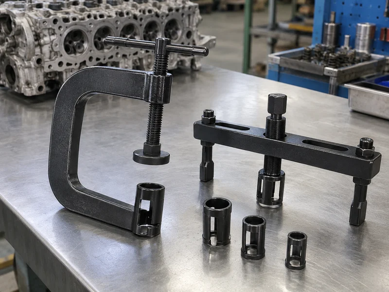
These tools are for engine valve springs. They are not suspension coil-spring compressors, which hold much larger vehicle springs through different fixtures and procedures. Nor does “universal” prove fit across head designs. Engine family, valve layout, spring depth, retainer diameter, and tool mounting points determine whether a compressor can sit squarely.
Start with the service context:
- Head on engine or head removed and supported on a bench.
- Overhead-valve, overhead-cam, or another documented layout.
- Retainer shape, spring position, and clearance above the head.
- Manufacturer-approved method for keeping or supporting the valve.
Choose by reaction point first. Ask for the compressor’s application list and a drawing that shows where its force enters and exits.
Compressor family matrix
| Tool family | Typical support arrangement | Buyer fit question |
|---|---|---|
| Overhead jaw or lever | Reaches a spring with head installed | Does the jaw and valve support match this head? |
| Bolt-on head-mounted lever | Attaches at specified engine points | Do mounting points and cam layout match? |
| Bench C-frame | Head removed and supported in fixture | Does throat, foot, and frame reach the valve? |
| Offset-jaw bench tool | Jaws offset around a recessed spring | Does offset geometry clear the casting? |
2. How does an on-engine overhead jaw compressor work?
An on-engine overhead tool reaches the spring and retainer from above. Depending on design, jaws engage the spring and a lever or screw compresses it. Some tools require a separate valve-holding method because the head remains installed and the valve could move when its keepers release. A specific manufacturer may call for a compatible air-hold fitting or another procedure. That requirement belongs to that engine and tool combination, not to every overhead compressor.
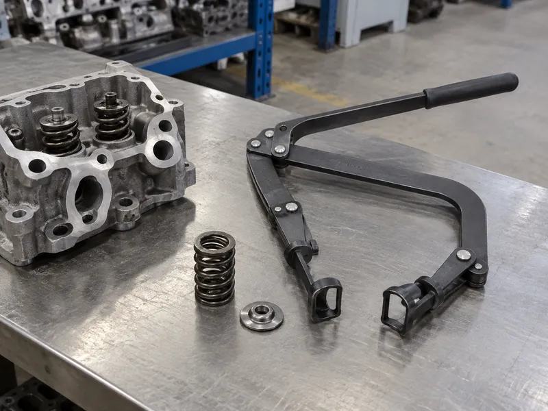
Fit depends on jaw reach, throat depth, spring position, rocker or cam hardware, and room to operate the handle. The tool must seat on intended contacts rather than slip off a coil or load a nearby part. One overhead model’s instructions pair its compressor with separate air-hold accessories; this does not set a universal pressure or procedure.
Describe included parts and exclusions. Match any cylinder connection by thread, sealing method, reach, and the engine service procedure. A fitting that screws into an opening can still have incorrect reach or seal geometry.
- Confirm the engine and head position named in instructions.
- Check jaw reach and spring contact on an approved sample.
- Identify any separate valve support or holding accessory.
- Keep pressure and positioning instructions model-specific.
Treat the holding method as part of the kit. List required accessories separately when they are not included.
On-engine compressor checks
| Check | What to confirm | Buyer record |
|---|---|---|
| Head application | Engine layout and mounting access | Approved model list |
| Jaw engagement | Contact on intended spring area | Fit photo or sample check |
| Valve support | Procedure and required accessory | Exact manual reference |
| Handle path | Clearance around nearby parts | Application image |
3. When does a bolt-on lever tool suit an overhead-cam head?
Some overhead-cam tools bolt to specified head locations and use a lever or threaded member to press a retainer. Bolt spacing, cam supports, valve angle, and tool geometry must match. A photo cannot prove compatibility.
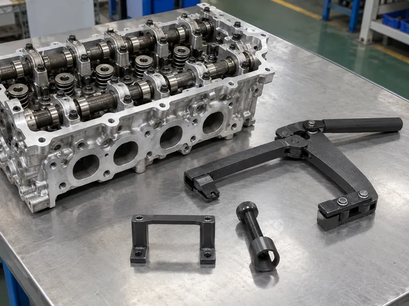
A tool may require cam caps, brackets, studs, or a special adapter. Read the instructions for permitted installation points and component removal. One product manual uses a block attached at cam-cap locations for a defined layout. That is not a general mounting rule; do not substitute unapproved bolts or bridges.
The automotive repair tools range includes engine-service products; use its category context while checking model-level fit. Keep mounting-fastener tools separate from compression adapters when planning an engine-service kit. The hand tools range provides options for those supporting wrenches and drivers; their inclusion does not extend compressor compatibility.
- Request the supported engine family and mounting location.
- Check bolt thread, depth, spacing, and clearance from cam hardware.
- Verify the pressure member centers on the retainer.
- Confirm whether required brackets or adapters ship in the kit.
Mounting details decide compatibility. Require a marked head drawing and a model-specific instruction sheet before approving a bolt-on compressor.
Head-mounted lever fit matrix
| Interface | Fit requirement | Evidence to request |
|---|---|---|
| Mounting points | Approved holes and spacing | Application drawing |
| Fasteners | Correct thread and engagement | Part list and instructions |
| Lever alignment | Contact centered over retainer | Working-position image |
| Included hardware | Brackets, studs, adapters | Box contents checklist |
4. Why use a bench C-frame compressor with the head removed?
A bench C-frame spans a removed head. One contact supports the valve side while a pressure foot reaches the retainer. Screw, lever, or ratcheting mechanisms vary; jaw width, throat depth, and frame opening determine reach.
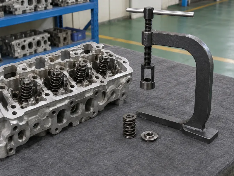
The removed head needs stable support and valve clearance. One bench-tool manual calls for test-fitting straight or offset jaws and aligning the push rod with the valve. Other tools differ, so follow the applicable manual.
Bench tools serve removed heads; they do not automatically replace on-engine tools. Use the specified fixture and frame, never a homemade jig.
- Check throat depth against spring recess and head thickness.
- Support the head so it cannot rock or contact the valve tip incorrectly.
- Test-fit the selected jaw before loading the spring.
- Confirm the pressure foot reaches the retainer without touching adjacent parts.
The frame has to close on the right points. Approve head-off tools with a supported sample head or a dimensioned fixture drawing.
Bench-frame comparison
| Feature | Buyer question | Warning sign |
|---|---|---|
| Throat depth | Can tool reach recessed spring? | Frame collides with casting |
| Frame opening | Does head fit within frame? | Head cannot sit stable |
| Jaw shape | Straight or offset contact needed? | Jaw hits coil or retainer edge |
| Pressure foot | Does it center on retainer? | Foot contacts valve or keeper |
5. When do offset jaws or adapters matter?
Offset jaws and adapters can reach recessed springs or different retainer profiles. Use the contact specified by the maker. An offset may change the load line, so check alignment and stability.
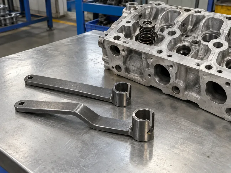
A kit’s adapter range should be explicit. Request dimensions, applications, jaw width, contact depth, and instructions. One compressor manual selects between two release adapters and keeps them clear of keepers; a bench-tool manual calls for test-fitting straight or offset jaws. Adapter choice belongs to the tool and engine application.
Do not assume a cup that fits one retainer also clears its keepers. Nor should a catalog claim “fits all” based on a few jaw widths. Record retainer contact diameter and keeper-window clearance separately. Two adapters with equal outside diameters may leave different working room around the keeper.
- Compare contact diameter and opening against a verified retainer.
- Confirm jaw width and offset with the head casting in place.
- Check that keepers remain accessible during the approved operation.
- Label adapters so each part maps to a documented application.
Fit the contact before loading it. Request an adapter chart and images of each approved working position.
Jaw and adapter matrix
| Adapter feature | Fit question | Approval evidence |
|---|---|---|
| Contact diameter | Does it bear on the intended retainer area? | Measured sample |
| Offset | Does it clear the casting and stay aligned? | Side-view fit check |
| Opening | Does it clear keepers as instructed? | Manual and sample |
| Identification | Can each adapter be distinguished? | Part marking or tray map |
6. How do retainer and keeper geometry set fit?
The compressor presses the spring retainer while keepers or locks are exposed for service. The tool’s release adapter needs enough clearance for those parts. A cup that is too narrow may obstruct keeper access; one that is too wide or poorly centered may load an unintended surface. A spring’s outside diameter alone cannot establish compatibility because the retainer, valve tip, keeper arrangement, and head clearance all shape the contact.
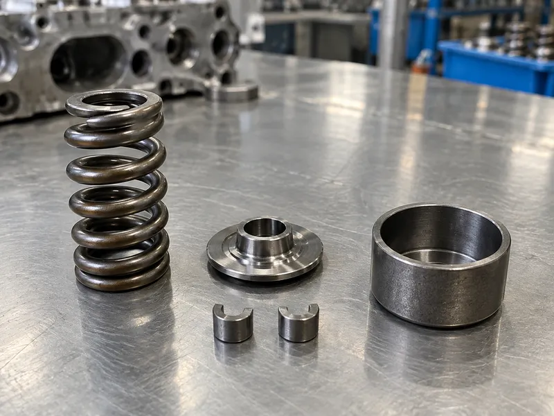
Review a cross-section showing compressor, spring, retainer, and valve. Confirm pressure-foot contact, head support, and keeper access. One tool manual specifies a cup against the valve and an adapter over the retainer; other designs may differ.
Name each adapter and its scope; retainer profiles vary by engine. The complete mechanic tool list can help place engine tools within a broader assortment, while the compressor listing must show its own head and retainer fit.
- Compare the tool contact with a real retainer and keeper layout.
- Check that keeper access remains clear at the required compression.
- Verify valve support and head stability from the manual.
- Record adapter part numbers and their approved applications.
Retainer access is part of fit. Approve the full working assembly, not an isolated jaw measurement.
Retainer-interface matrix
| Part | Contact or access requirement | Buyer check |
|---|---|---|
| Spring | Tool must engage at intended location | Coil and seat clearance |
| Retainer | Pressure surface stays centered | Diameter and profile |
| Keeper or lock | Must remain accessible per procedure | Adapter opening and travel |
| Valve | Support point follows tool instructions | Head position and contact |
7. How do head position and valve holding change setup?
Head-on and head-off work need different support. With the head installed, follow the engine-approved method for holding the valve as keepers release. Procedures vary; there is no universal air pressure or connection for all engines.
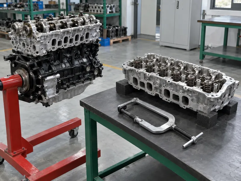
With a removed head, support it securely and leave room for valve travel. Do not load an unsupported casting or use the tool outside its design. Follow both engine and compressor instructions.
Confirm what happens if the specified holding support is lost. The work instruction should explain how the operator unloads the compressor and secures the assembly before changing any fitting or support.
- Identify whether the head stays installed or is removed.
- Follow engine-specific instructions for valve support or piston position.
- Use only the specified air-hold accessory and pressure procedure, if required.
- Support the removed head before loading a bench compressor.
Keep the procedure tied to the engine. Follow the documented pressure, piston position, and support arrangement for that application.
Setup decision table
| Setup | Support issue | Required documentation |
|---|---|---|
| Head installed | Valve must remain controlled when keepers release | Engine procedure and tool manual |
| Head removed | Head and valve need stable bench clearance | Fixture and compressor instructions |
| Air-hold method specified | Connection and pressure are model-specific | Approved fitting and service procedure |
| Alternative holding method | Engine-specific limits apply | Manufacturer’s service information |
8. What safety and quality checks control spring load?
A compressed spring stores energy. A slipping jaw or sudden release can eject parts or damage the head. One manufacturer manual calls for eye protection and unloading the compressor before removal. Buyers need product-specific safety directions.
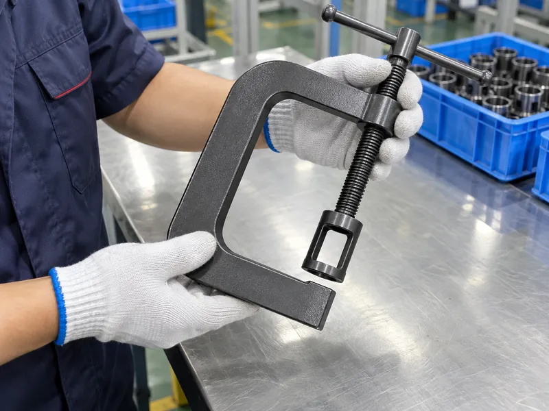
During sample review, check the frame, threads, pins, locking parts, jaws, adapters, and contact faces. Confirm smooth adjustment without binding and inspect whether the tool holds its position under the maker’s stated procedure. Do not create an improvised overload test. Product testing should use a defined fixture and acceptance criteria supplied by the manufacturer. Keep hands clear of pinch points, control the loaded tool, and follow the engine manual throughout service.
- Check castings, welds, threads, pins, jaw faces, and handles for defects.
- Confirm safety instructions identify stored spring energy and release steps.
- Check that the supplied instructions explain eye protection and the approved valve-holding method.
- Quarantine a damaged or modified compressor.
A sample is only useful with a safe test plan. Ask for the inspection method, product revision, and written operating instructions. Review Kolarwin’s company information when identifying who will supply application documentation and handle technical questions.
Safety and quality matrix
| Review point | Evidence | Stop condition |
|---|---|---|
| Frame and contact parts | Visual check and drawing | Crack, bend, loose joint, or mismatch |
| Threaded mechanism | Smooth travel under stated method | Binding, damaged thread, or unintended release |
| Position retention | Function check per instructions | Lock or detent does not hold as specified |
| Safety content | Product-specific manual | Missing load-release directions |
| Sample traceability | ID and revision record | Test result cannot be tied to SKU |
9. How should distributors compare compressor samples?
A fair comparison uses the same approved head, spring assembly, operating method, and inspection record for each candidate. Compare contact alignment, access to keepers, handle or screw path, stability, adapter changes, and release control. Do not compare one tool on a head-on procedure with another on a bench fixture and call the result a product ranking.
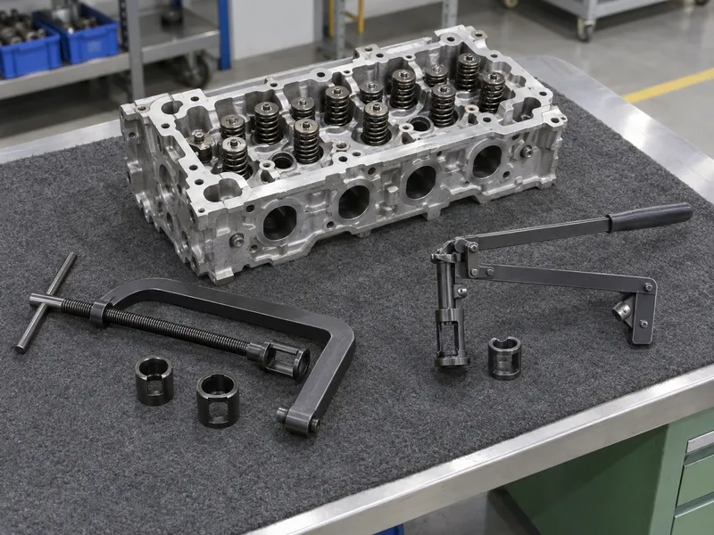
Request the exact application range and all exclusions. Check replacement adapters, storage, spare parts, instructions, and packaging. A sample reveals fit only for its demonstrated application. The automotive repair tool guide for must-have categories supports broader assortment planning. The mechanic tools list can help position engine-service SKUs without implying universal application.
- Compare like-for-like head configuration and spring assembly.
- Record every adapter, mounting point, and tool revision.
- Tie application claims to service data or maker instructions.
- Keep unverified engines out of the approved range.
Make the sample repeatable. Write down fixture, head, adapter, method, observations, and acceptance before comparing suppliers. Use the wholesale supplier selection checklist to record responsibility for replacement adapters, drawing revisions, and repeat-order consistency.
Sample comparison table
| Comparison field | What to record | Why it matters |
|---|---|---|
| Head and engine | Position, layout, application | Establishes a fair comparison |
| Tool contact | Jaw, foot, adapter, support point | Shows load alignment |
| Operation | Lever, screw, mount, release | Captures handling differences |
| Parts and records | Adapter list, manual, revision | Keeps approval traceable |
10. What should a valve spring compressor RFQ include?
An RFQ should name the target engine families and whether the cylinder head remains installed. Include head layout, spring and retainer dimensions, mounting points, access limits, approved valve support, adapters, and work location. Attach photographs or drawings that show both sides of the head and the available tool path.
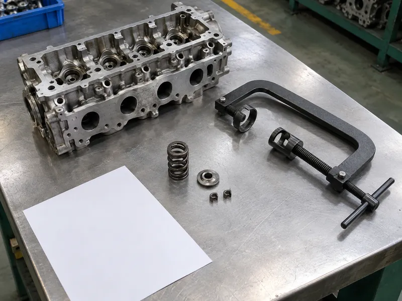
Ask the supplier to identify included hardware, excluded accessories, instructions, spare parts, inspection records, and application evidence. Require the approved fixture and engine-specific valve-holding procedure. Accept compatibility statements only for applications supported by the engine and tool instructions. Keep suspension spring compressors out of the valve-tool scope.
- List engine and head references, not only vehicle model names.
- Request a dimensioned drawing and sample-fit plan.
- Define safety documentation and adapter traceability.
- Approve final listing language against verified applications.
Specify the complete working setup. Send head drawings, retainer samples, required access, and the intended service method through the Kolarwin inquiry page with the RFQ.
Q1: Does one valve spring compressor fit every engine? No. Head layout, mounting points, spring recess, retainer, and instructions vary.
Q2: Can an on-engine compressor work with the head removed? Only if its instructions approve that setup and support method.
Q3: Is a valve spring compressor the same as a suspension coil-spring compressor? No. They serve different springs and use different fixtures.
Q4: Is there one air pressure for holding every valve? No. Follow the engine and tool instructions for any approved air-hold method.
Q5: What should a buyer verify before ordering? Engine application, head position, contact geometry, accessories, instructions, and sample-fit evidence.
Looking for a reliable mechanic tools manufacturer in China?
If you are sourcing hand tools, socket tools, automotive repair tools, mechanic tool sets or OEM private label tools, contact KOLARWIN Tools for factory-direct quotation, customization support and product consultation.