Need OEM supplier support for this product type?
Contact KOLARWIN Tools for OEM mechanic tools, private label packaging, wholesale quotation and product range support. This gives overseas buyers a clear path from article reading to supplier discussion.
Brake-service buyers often face a simple choice: pull fluid from each bleeder screw with vacuum or push fresh fluid from a sealed reservoir with pressure. The right answer depends on vehicle procedure, adapter fit, fluid control and shop throughput. This guide gives buyers a fit-first framework grounded in maker instructions and OEM service records.
1. What is the core mechanism behind vacuum and pressure bleeding?
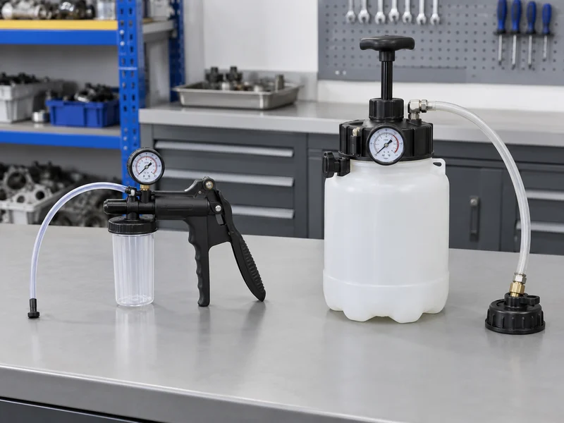
Vacuum equipment creates lower pressure at a wheel bleeder. Fluid and air move through a hose into a catch bottle while a pump or shop-air venturi unit holds the pull. Pressure equipment seals onto a reservoir and pushes fluid toward an opened bleeder. A regulator, relief valve and shutoff control supply. Both methods move fluid, yet expose faults.
A vacuum-bleeder manual shows a pump, reservoir, clear hose and fitted bleeder connection. It warns against drawing fluid into the pump and instructs operators to keep the master-cylinder reservoir filled. Pressure bleeders connect a fluid supply to a sealed reservoir adapter.
Match the fluid path to the vehicle’s service procedure.
- Vacuum acts at a wheel bleeder and needs a tight hose or cup.
- Pressure acts at a reservoir opening and needs a stable cap seal.
- Both methods need a clear recovery path.
Draw a one-page fluid-path sketch for each vehicle family before comparing pump prices. Mark where fluid enters, where air could enter and where an operator can see the flow.
Decision table
| Check | Vacuum method | Pressure method |
|---|---|---|
| Force location | Bleeder screw | Master-cylinder reservoir |
| Main seal | Hose, cup or screw adapter | Reservoir cap and gasket |
| Common visibility | Hose and catch bottle | Recovery hose and tank level |
| Buyer risk | Tool-side air mistaken for system air | Wrong cap or supply |
2. Which vacuum bleeder types fit different shop jobs?
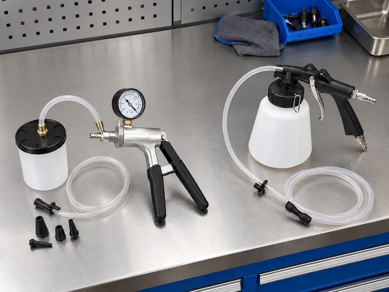
Hand-pump kits suit low-volume service, mobile technicians and shops without compressed air. A jar protects the pump. Shop-air units use a venturi effect and trigger, reducing hand pumping. Powered systems support throughput, yet hoses, noise and air demand deserve review.
An adapter kit matters as much as the pump. Tapered and 90-degree adapters can serve wheel-cylinder, caliper and master-cylinder applications, while a rubber fitting can sit on a bleeder screw. “Universal” still needs a coverage sheet. A rubber cup may seal on one screw head, then admit air around another.
Check the fitting before comparing pump capacity.
- Hand pump: portable, quiet and easy to inspect.
- Shop-air venturi: fast repeat cycles, with compressor dependence.
- Powered unit: higher workflow capacity, with added service parts.
Record wheel positions, bleeder shapes, hose lengths, air supply and daily vehicle count. Use that sheet to choose a pump architecture.
Decision table
| Vacuum format | Good fit | Questions for sourcing |
|---|---|---|
| Hand pump | Mobile or low-volume work | Gauge, jar, hose and adapter sealing |
| Shop-air | Repeated bay service | Air demand, trigger, relief and noise |
| Powered | Higher throughput | Service parts, power input and filtration |
For a wider automotive repair tools range, group brake equipment with the fittings and fluid-control tools that make each workflow usable.
3. How does a pressure tank change brake bleeding?
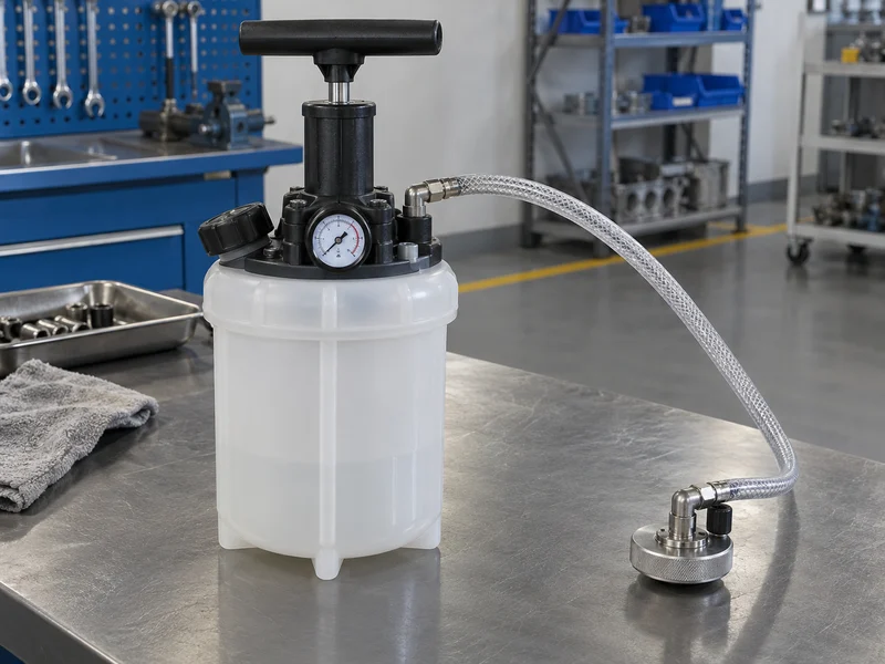
A pressure tank controls fluid supply. The operator fits a reservoir cap, opens supply and controls flow with a regulator or valve. A shop-air suction tank remains a vacuum bleeder even when its tank includes a relief valve.
Pressure can reduce hand pumping and ease repeated wheel service. It can also expose a poor cap seal: fluid leaks at the reservoir or the tank loses pressure before flow. Tank construction, wetted seals, hose fittings and unused-fluid handling deserve attention.
An OEM record hosted by NHTSA describes a pressure-bleeding procedure that uses a specified reservoir cap, clear recovery hose and fluid-level checks. This shows why a tank gauge cannot replace a vehicle instruction.
Specify pressure control and reservoir sealing together.
- Confirm tank material and seal compatibility.
- Ask how a relief valve is tested and reset.
- Specify whether fresh fluid travels through the tank.
Request a pressure curve, relief-test record and cap-seal sample for every private-label tank.
Decision table
| Pressure feature | Buyer question | Evidence to request |
|---|---|---|
| Regulator | How does an operator set and hold supply? | Gauge check and operating file |
| Relief valve | What prevents excess pressure? | Test method and replacement part |
| Reservoir cap | Which necks and seals fit? | Adapter matrix and sample trial |
| Fluid path | Can fresh fluid remain clean? | Material and cleaning guidance |
4. Which reservoir adapters decide compatibility?
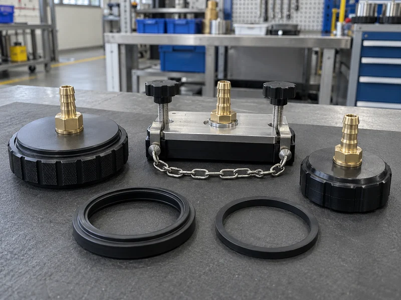
The reservoir cap controls whether a pressure bleeder can do its job. Threaded caps match a known neck. Universal rubber adapters depend on surface shape and compression. Plate retainers use a base, gasket and clamp force. A vacuum-system auto-filler replenishes fluid; its retainer is not automatically suitable for pressurizing a reservoir. A good kit combines clear identification with a way to replace worn seals.
Cap selection should cover neck diameter, thread form, lip height, reservoir vents and hose loading. A cap that seals on a bench may twist under hose tension. A rubber seal may collapse after contact with unapproved fluid. Buyers should check whether an adapter can be cleaned without trapping old fluid in a groove.
Approve each cap on its intended reservoir.
- List reservoir photos and measurements by vehicle family.
- Check cap stability while the hose is routed as used.
- Keep replacement gaskets and caps available.
Build an adapter coverage matrix with neck shape, seal material, hose angle, fit result and replacement part number.
Decision table
| Adapter type | Strength | Watch point |
|---|---|---|
| Threaded cap | Repeatable fit on known neck | Thread and vent variation |
| Bayonet or locking cap | Matches a defined reservoir neck | Tab, seal and locking variation |
| Plate retainer | Adjustable reservoir coverage | Uneven clamp or gasket pressure |
| Vehicle-specific cap | Strong procedure match | More SKUs and spares |
For adapters using a specified hex or square drive, check the required socket drive size before adding service tools.
5. What fluid compatibility and cleanliness controls matter?
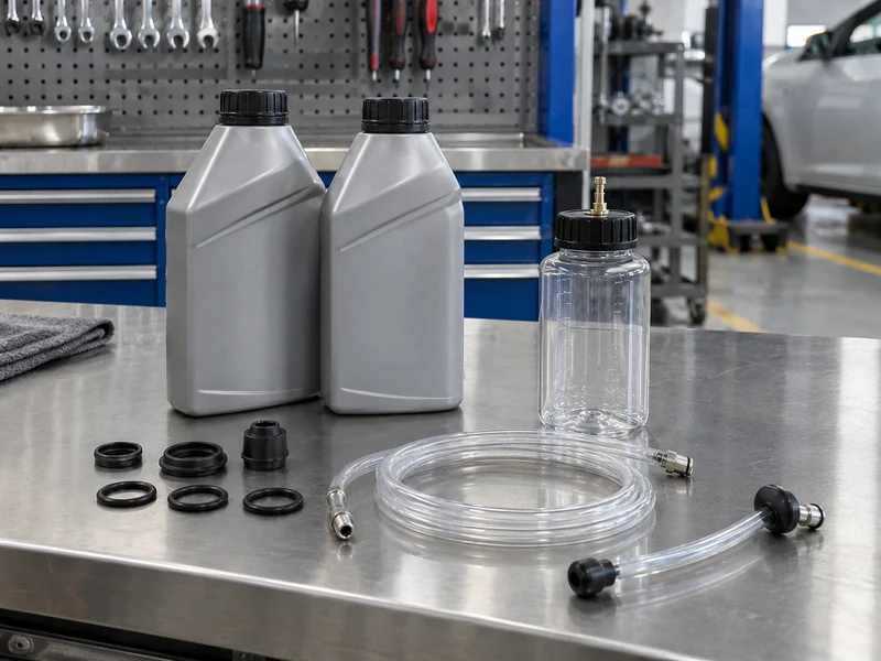
Brake fluid selection follows vehicle documentation. A tool listing does not authorize fluid mixing, storage or reuse. Buyers should identify the intended DOT specification, then ask which hoses, seals, tank coatings and pump parts contact fluid. A clear bottle can reveal old fluid and sediment, yet it cannot prove compatibility. Confirm material claims through product documentation and sample testing.
Keep brake-fluid supply equipment separate from tools used for motor oil, transmission fluid or other incompatible fluids. Confirm compatibility before changing fluid families.
Separate clean-fluid and waste-fluid paths reduce mistakes. Hoses should drain fully before storage. A maker manual may specify water-only cleaning for certain components, while another product may have different instructions. A pressure tank that carries fluid through a long hose needs a purge or replacement procedure when a shop changes fluid type. Packaging should keep caps, seals and transparent tubing free from dust.
Keep fresh-fluid equipment clean and correctly assigned.
- Mark fresh-fluid and recovery containers by use.
- Ask for wetted-material declarations.
- Include replacement hoses, seals and cleaning instructions.
Add a fluid compatibility table and cleaning sequence to the RFQ, then keep unresolved materials outside any published specification.
Decision table
| Control | Why buyers need it | Proof |
|---|---|---|
| Fluid specification | Prevents unsupported mixing | Vehicle and maker reference |
| Wetted materials | Protects seals and hoses | Material declaration |
| Cleaning method | Reduces carryover | Written process and sample |
| Storage | Keeps dust and residue out | Cap, case and replacement plan |
See the broader complete mechanic tools list when building a workshop range around brake service.
6. Why do false bubbles appear, and where are the diagnosis limits?
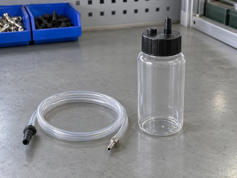
Vacuum bleeding can pull air around bleeder-screw threads, a loose rubber cup or a hose connection. A hose can also move against a rough fitting. The result looks like air from the brake circuit even though the leak sits at the tool interface. During pressure bleeding, a loose reservoir adapter can leak fluid or lose pressure. It does not explain recovery-hose bubbles by itself. Fluid agitation and a partly filled container can add small bubbles too.
Diagnosis starts with the interface. Lubricating a bleeder-thread area may reduce tool-side air in a maker's procedure, yet that step must follow product and vehicle guidance. A stable hose, sealed cup and clear container make the stream easier to interpret. A steady stream does not prove every ABS chamber is clear.
Check for tool-side air before interpreting the bubbles.
- Repeat a short draw with the same hose and a new seal.
- Compare bubbles before and after tightening the interface.
- Keep vehicle and scan-tool checks separate from visual flow.
Write a three-stage diagnosis card: tool-side leak check, base-brake flow check and vehicle-specific final check.
In the wider hand tools category, keep hose and fluid accessories matched with the bleeder range.
Decision table
| Observation | Possible source | Next check |
|---|---|---|
| Bubbles only at cup | Adapter or thread leak | Reseat or change fitting |
| Foamy fluid in bottle | Agitation or hose movement | Stabilize hose and container |
| No flow | Closed screw, blockage or poor seal | Inspect screw and cap path |
| Firmness still uncertain | Vehicle or ABS condition | Follow service procedure |
7. How do ABS and OEM procedures change the equipment decision?
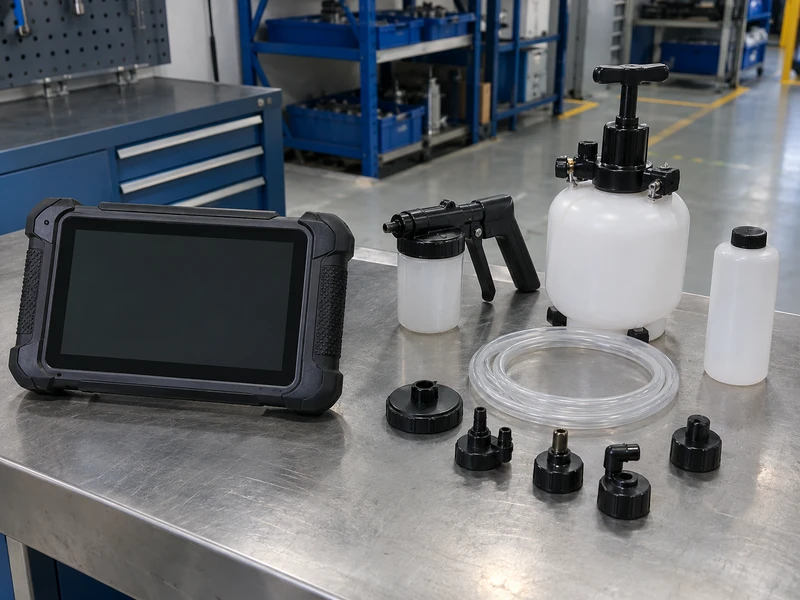
ABS introduces hydraulic-control-unit passages and electronic routines that a simple wheel bleed may not reach. An OEM service record hosted by NHTSA states that base brakes and the ABS portion should be treated as separate systems. It calls for a scan-tool function, then a repeat base-brake bleed. The procedure remains model-dependent and should define any applicable pressure value.
Select equipment by vehicle procedure, not by a claim that vacuum or pressure works on every car. A mixed-fleet shop may need pressure, vacuum, caps, scan-tool access and a procedure library. Distributors should avoid printing a universal sequence or pressure value.
Let the OEM procedure define ABS equipment coverage.
- Separate base-brake and ABS workflow documents.
- List scan-tool and adapter requirements by vehicle family.
- Keep fluid-level and recovery checks visible at the bay.
Ask buyers for target models, then map each model to pressure, vacuum, scan-tool and cap requirements before quoting.
Decision table
| Service condition | Equipment implication | Wording limit |
|---|---|---|
| Base brake only | Vacuum or pressure may fit procedure | Follow vehicle manual |
| Air in ABS unit | Scan-tool routine may be required | Not a generic DIY step |
| Mixed fleet | Multiple caps and methods | No universal sequence |
| OEM procedure | Exact pressure and order | Keep source-specific |
8. What QC evidence should a brake-bleeder buyer request?
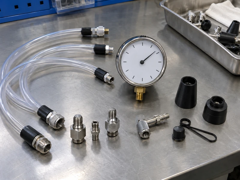
QC should test the complete fluid path, not only a pump body. Inspect cap threads, gasket compression, hose barbs, shutoff action, gauge response, reservoir seams and relief-valve behavior. A leak test should hold the intended condition for a documented period. A flow test should use a stated fluid substitute or approved fluid and identify the adapter used. Photos help, yet a buyer needs records that connect a sample to a lot.
Packaging QC matters too. A kit may pass a bench test and still arrive with cracked tubing, mixed cap labels or a missing seal. Spare parts need reorderable identifiers. Maker instructions should state what an operator inspects before service. Avoid unsupported accuracy, pressure or universal-fit claims.
Record enough test detail to reproduce the result.
- Record sample identity, adapter and test medium.
- Inspect gauge, relief and leak behavior separately.
- Photograph seals, case layout and markings.
Place leak, flow, gauge, relief and adapter checks in the purchase specification with acceptance criteria agreed before production.
Decision table
| QC item | Sample check | Buyer record |
|---|---|---|
| Adapter seal | Hold fluid path without leakage | Fit result and photo |
| Gauge | Compare against reference | Reading and instrument ID |
| Relief valve | Confirm release behavior | Test condition and result |
| Hose and tank | Inspect flow and seams | Lot and sample trace |
9. How should a shop or distributor configure a brake-bleeding range?
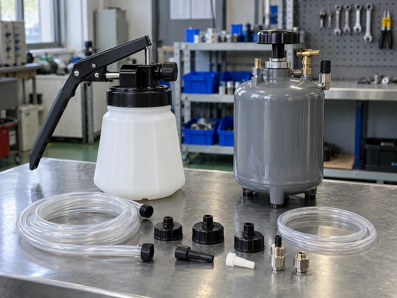
An entry range can begin with a hand vacuum kit, recovery bottles, adapters, spare hose and seals. A pressure range adds a tank, regulator, relief valve and reservoir-cap matrix. Busy shops may add a shop-air vacuum unit or auto-filler. The assortment should reflect jobs, compressor availability, training and storage.
Distributors should avoid packing unrelated accessories into a large case merely to raise piece count. A buyer benefits from a clean path: select adapter, connect pump, control fluid, recover fluid and replace seals. Product labels can identify SKUs while technical sheets carry the fit matrix. Packaging should leave room for procedure cautions.
Give every cap, hose and spare a defined application.
- Entry kit for mobile and low-volume buyers.
- Pressure kit for repeated service and fresh-fluid control.
- Adapter and seal refill packs for after-sales support.
Model expected jobs per week, then quote a base kit plus serviceable add-ons instead of one oversized assortment.
Decision table
| Buyer profile | Core range | Add-ons |
|---|---|---|
| Mobile technician | Hand vacuum kit and bleeder fittings | Spare jars and hoses |
| General shop | Vacuum and pressure options | Adapter matrix and seal packs |
| Fleet or high volume | Pressure tank and auto-filler | Procedure files and replacement parts |
For larger programs, use the mechanics tool set range to plan storage and the supplier profile to assess company fit.
10. What should a brake-bleeder RFQ include?
An effective RFQ names vehicle families, base-brake and ABS coverage, fluid specification, tank or pump format, air or power source, reservoir-neck samples, hose length, adapter count, seal material, cleaning method and spare parts. It also asks for operating instructions, leak and relief tests, sample photos and packaging details. If a buyer expects private label, add artwork limits, carton marks, replacement identifiers and document language.
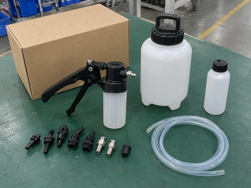
Ask a supplier to test three interfaces: a common cap, a tight-access bleeder and a vehicle-specific adapter. Request the result with sample ID and test medium. A pilot order can check fit, flow and fluid handling. Keep pressure values and bleed order tied to source procedures.
Send the interface and test requirements with the RFQ.
- Attach reservoir photos and thread measurements.
- List the target fluid and cleaning method.
- Request QC records and replacement parts.
- Confirm which claims belong to the tool maker or vehicle maker.
Send the RFQ with your adapter matrix, sample test plan and document checklist. Use the wholesale supplier checklist during supplier review, then contact the Kolarwin contact team.
Q1: Is a vacuum brake bleeder better than a pressure bleeder?
Neither method wins for every vehicle. Match force direction, adapter fit, fluid path and maker procedure to each service family.
Q2: Can I use one pressure setting on every vehicle?
No. Pressure and sequence can vary by vehicle or service procedure. Keep any published value tied to its source.
Q3: Do bubbles always mean air remains in the brake system?
No. Vacuum can draw air around bleeder threads, cups or hose joints. Isolate tool-side leaks before diagnosing the hydraulic circuit.
Q4: Does ABS bleeding always require a scan tool?
ABS service is model-dependent. Some procedures use a scan-tool routine for the hydraulic control unit, so confirm the applicable OEM instructions.
Q5: What should a distributor request from a factory?
Request adapter coverage, fluid compatibility, leak tests, sample results, spares and clear claim limits.
Looking for a reliable mechanic tools manufacturer in China?
If you are sourcing hand tools, socket tools, automotive repair tools, mechanic tool sets or OEM private label tools, contact KOLARWIN Tools for factory-direct quotation, customization support and product consultation.